CAE Integration
Into NPD Workflow
Simulation shouldn't merely validate finished designs—it must actively steer every engineering decision from concept initiation to production freeze. APJ 3D delivers premier CAE NPD Integration India, embedding structured CAE in Product Development Process workflows across modern Digital Engineering NPD India ecosystems.
Interactive Pipeline Shifter Track
Drag and select milestone nodes along the NPD track to observe ROI multiplier variance.
Gate 01: Concept Architecture
Driven by CAE in Product Development Process and CAE NPD Integration India.

Handoff Protocol Bridge Deck
Interactive protocol cards establishing direct synchronization between native CAD and finite element solvers.
Direct Associative Link
CATIA V5 / Siemens NX Native Sync
Mid-Surface Shell
HyperMesh Shell Generation
Bi-Directional Loop
ANSYS Multi-Physics Solver
Throughput: Real-time geometry updates without loss of feature trees or assembly hierarchy.

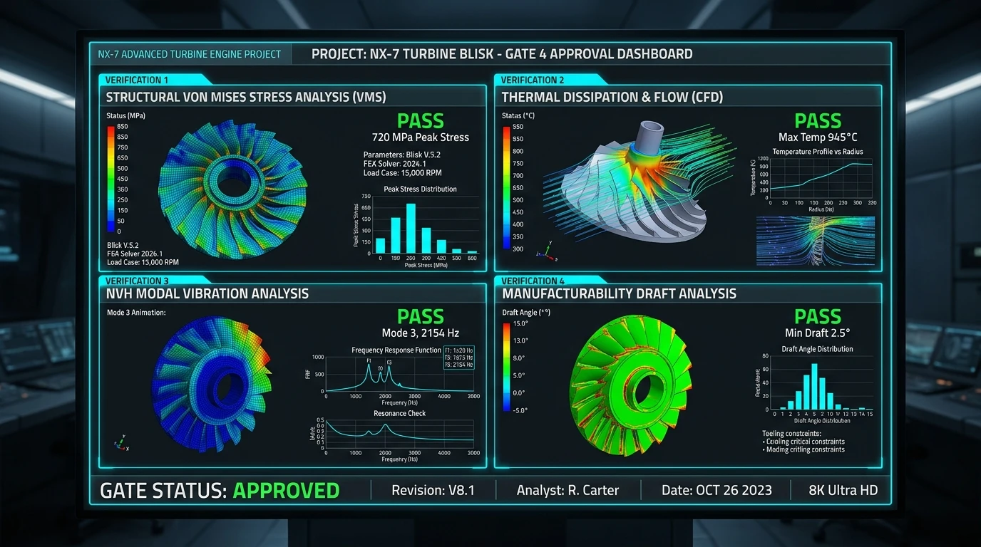
2x2 Approval Gate Matrix Board
Interactive evaluation sector cards verifying multi-physics sign-off benchmarks.
Structural Integrity Check
✓ PASSED SIGN-OFFThermal Dissipation Check
✓ PASSED SIGN-OFFDynamic NVH Modal Check
✓ PASSED SIGN-OFFManufacturability Check
✓ PASSED SIGN-OFFStructural Integrity Gate

Vertical Tower Elevator Shaft
Interactive 3-level elevator shaft tracking CAD model complexity as engineering fidelity matures.
Floor 2: Detail FEA Optimization [Level 200]
Fidelity: Accurate parametric feature representation with sub-modeling around fillet stress risers.

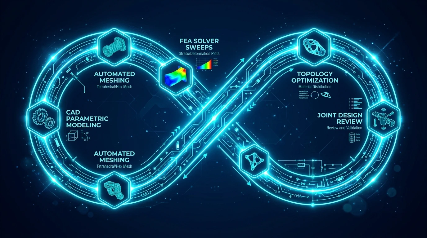
Infinity Loop Circuit Board
Select interactive circuit blocks along our closed-loop CAD-CAE collaboration loop.
Establishing quantifiable multi-physics performance budgets and operating envelopes.
Digital Engineering Command Hub
Futuristic command modules monitoring project deliverables across 9 premier industrial sectors.
Embedded Simulation Gates
Value: Zero late-stage prototype failures across 4,000+ completed NPD tasks.

What is CAE NPD Integration India?
CAE NPD Integration is the structured embedding of simulation (FEA and CFD) directly into the New Product Development workflow, so CAE actively steers design decisions from concept initiation through to production freeze instead of only validating a finished design at the end.
When to Select This Service
Choose CAE NPD integration when simulation is currently siloed as a late-stage checkpoint and you need it built into every design gate, from concept freeze reviews through to final production sign-off.
Technical Capabilities & Verification Standards
Verified engineering parameters, hardware precision, and compliance benchmarks applied across all deliverables.
| Engineering Parameter | APJ 3D Capability & Precision Range | Compliance Standard / Verification |
|---|---|---|
| Simulation Disciplines | Linear/Non-Linear Structural FEA, Thermal Analysis, CFD Fluid Dynamics, Crash & Impact, Fatigue & Durability, NVH | ISO 9001 / NAFEMS Validated Procedures |
| Solvers & Software | ANSYS Mechanical, Abaqus, Altair HyperWorks/OptiStruct, Moldflow, OpenFOAM, LS-DYNA | High-Performance Computing (HPC) Clusters |
| Material Models | Elastic-Plastic metals, Hyperelastic rubbers, Composites, Viscoelastic polymers, Temperature-dependent curves | Tested Material Property Databases |
| Mould Flow Capabilities | Fill time, injection pressure, weld line prediction, sink marks, cooling circuit efficiency, volumetric shrinkage & warpage | Autodesk Moldflow Insight Validated |
| Deliverables | Comprehensive Engineering Reports, Von Mises Stress Plots, Factor of Safety (FoS) Maps, Deformation Animations, Optimization STEPs | Actionable Design Recommendation Summaries |
| Model Scale | From precision micromixers and plastic clips up to full vehicle chassis and industrial equipment weldments | Multi-Million Degree-of-Freedom Meshes |
| Turnaround Time | 3 to 7 business days for standard FEA/CFD studies; 24–48h for urgent gate location & fill checks | Dedicated Senior CAE Analysts |
Frequently Asked Questions
What information is required to start an FEA or CFD simulation?
What information is required to start an FEA or CFD simulation?
How do you validate the accuracy of simulation results?
How do you validate the accuracy of simulation results?
How can Moldflow simulation save tooling costs for plastic parts?
How can Moldflow simulation save tooling costs for plastic parts?
Can you optimize parts for lightweighting and material reduction?
Can you optimize parts for lightweighting and material reduction?
What is included in the final simulation report?
What is included in the final simulation report?
Make Simulation Part of Every Engineering Decision
Transform your product development pipeline with premier CAE NPD Integration India and structured CAE Workflow Setup India. Embed simulation gates across your entire Digital Engineering NPD India workflow.