Drawing-to-Production
Transformation
We convert CAD models into manufacturing drawings, and manufacturing drawings into comprehensive shop floor packages that eliminate setup guesswork and rework.
The drawing that gets approved
isn't always the drawing that gets used.
The gap between design intent and production reality causes delays, rework, and endless clarification calls. Here is the difference.
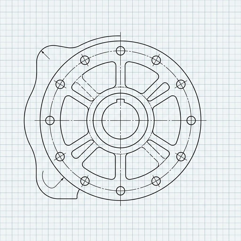

What a Shop Floor Drawing Must Get Right
Hover over the focal points below to reveal the core data critical for manufacturing.
Services Delivered to the Shop Floor
CAD Translation
CAD Model Exists. The Machinist Still Can't Use It.
Drawing Cleanup
Fixing existing drawings that aren't ready for production.
Tolerance Def
Applying GD&T mapped to your machine capabilities.
Fabrication Details
Structural Fabrication Jobs With Fixed Start Dates.
Production Package
Final release packet ready for the shop floor.
Drawing Conversion & Rebuild Process
Slide across the timeline to magnify each step of our engineering process.
We analyze your current state data to map out missing information.
We analyze your current state data to map out missing information.
Evaluating machining feasibility and setup requirements.
Evaluating machining feasibility and setup requirements.
Placing dimensions exactly how the machinist will probe the part.
Placing dimensions exactly how the machinist will probe the part.
Applying strict tolerances only where functional fits require them.
Applying strict tolerances only where functional fits require them.
Delivery of the final, unambiguous production package.
Delivery of the final, unambiguous production package.
Who Sends This Work To APJ 3D
Machine Shops
Fabricators
Tooling Suppliers
The Drawing Is Where Production Starts Right or Starts Wrong
Poor blueprints guarantee bottlenecks. See how APJ 3D’s precision manufacturing drawings dramatically shift the dynamics on the shop floor. Hover over the data bars to see the impact.
What is Manufacturing & Shop Floor Drawing Services India?
CAD Modeling and Drafting is the digital creation of parametric 3D solid models, sheet metal flat patterns, and 2D manufacturing blueprints with comprehensive GD&T callouts, datum schemes, and Bills of Materials (BOMs).
When to Select This Service
Choose parametric CAD drafting when converting legacy 2D drawings into native 3D solid models, detailing shop-floor blueprints per ASME Y14.5, or preparing tool-ready models for CNC machining and moulding.
Technical Capabilities & Verification Standards
Verified engineering parameters, hardware precision, and compliance benchmarks applied across all deliverables.
| Engineering Parameter | APJ 3D Capability & Precision Range | Compliance Standard / Verification |
|---|---|---|
| CAD Platforms | SolidWorks, Siemens NX, CATIA V5, Autodesk Inventor, Creo Parametric, AutoCAD | Native Feature Tree Formats |
| Drafting Standards | ASME Y14.5-2018, ISO 1101, ISO 128, DIN, JIS Standard Compliance | Full GD&T Tolerancing & Datums |
| Specialized Modeling | Class-A Surfacing, Complex Sheet Metal Flattening, Plastic Part Tooling DFM, Heavy Weldment Structures | Manufacturing-Ready Geometry |
| Drawing Deliverables | Fully Dimensioned 2D PDFs, DWG/DXF Flat Patterns, STEP AP242, Parasolid (.x_t), Native CAD Packages | Production-Ready Shop Blueprints |
| BOM & Documentation | Automated Hierarchical BOMs, Ballooned Assembly Drawings, Exploded Service Manuals, Hardware Catalogs | ERP-Ready Part Numbering |
| Quality Verification | Independent Senior Checker Review, Tolerance Stack-up Analysis, Interference & Clearance Checks | Zero-Defect Drafting Protocol |
| Turnaround Time | 24 to 72 hours for standard manufacturing drawing packages and CAD conversions | Scalable Dedicated Engineering Teams |
Frequently Asked Questions
Can you convert legacy 2D paper drawings or PDFs into 3D CAD models?
Can you convert legacy 2D paper drawings or PDFs into 3D CAD models?
Do your 2D engineering drawings include full GD&T callouts?
Do your 2D engineering drawings include full GD&T callouts?
How do you ensure sheet metal flat patterns account for bend allowances?
How do you ensure sheet metal flat patterns account for bend allowances?
Can you provide exploded views and assembly manuals for technical documentation?
Can you provide exploded views and assembly manuals for technical documentation?
What is the process for reviewing and revising drawing packages?
What is the process for reviewing and revising drawing packages?
Need Accurate Manufacturing Drawings for Your Parts?
Stop guessing dimensions on the shop floor. APJ 3D Delivers Production-Ready Manufacturing Drawings Across India.