2D Drafting & Manufacturing
Drawing
Services
Transform physical parts, scan data, and concepts into GD&T-compliant, production-ready manufacturing drawings. Built for the shop floor, not just the screen.
What Is 2D Drafting?
2D drafting is the process of turning a physical part, a 3D CAD model, or a scanned point cloud into a flat, dimensioned engineering drawing that a machine shop, quality inspector, or assembly line can act on directly. It works by projecting the true geometry of a component into orthographic and section views, then layering in dimensions, tolerances, GD&T callouts, surface finish symbols, and a title block so the drawing carries every instruction needed to make or inspect the part without further interpretation. Unlike a 3D model, which shows what a part looks like, a 2D drawing specifies exactly how it must be manufactured and measured.
This is different from reverse engineering, which recreates a 3D CAD model from a physical part or scan before any drawing is produced, and from raw 3D CAD design, which defines geometry but not shop-floor instructions. At APJ 3D, 2D drafting typically sits downstream of reverse engineering and upstream of documentation packages such as as-built drawings and a bill of materials, so a drawing request can start from a legacy print, a scanned part, or an existing 3D model.
2D Drafting
Converting verified geometry into GD&T-compliant, dimensioned production drawings — orthographic views, sections, tolerances, and title blocks ready for the shop floor.
Reverse Engineering
Rebuilding a 3D CAD model from a physical part, scan data, or point cloud. See our dedicated reverse engineering services for the upstream modeling step.
Documentation Packages
Complete drawing sets paired with as-built documentation and a structured BOM & parts list for production handoff.
2D Drafting vs. 3D-Only Workflows
A 3D CAD model alone doesn't tell a machinist how tight a bore tolerance must be or how a surface should be finished — that instruction layer only exists in a dimensioned 2D drawing.
Drawings That Work on the Shop Floor
A breakdown in engineering communication leads to massive manufacturing losses. Hover over the flow below to apply the APJ standard.
Measured Data
Structure
Logic
Documentation
Dimensions
Tolerances
Structure
Clarity
Complete 2D Drafting Capability Hub
Explore our comprehensive engineering documentation ecosystem designed for production. Hover across the ribbon below.
GD&T Engineering Drawings
ASME Y14.5 and ISO compliant geometric dimensioning and tolerancing for precision manufacturing.
Assembly & Exploded Views
Clear, sequential assembly instructions and exploded isometric views for manual and automated assembly lines.
Shop Floor Drawings
Machinist-friendly prints with clear datum references, finish callouts, and operation-specific views.
As-Built Generation
Updating master CAD drawings to reflect actual physical modifications made on the shop floor.
BOM & Parts Lists
Structured Bill of Materials, part numbering schemes, and comprehensive technical documentation packages.
Legacy Drawing Conversion
Digitizing and updating old paper blueprints, microfilms, or 2D CAD files into modern 3D associative drawings.
The Scan-to-Drawing Advantage
From physical site to flawless digital blueprints.
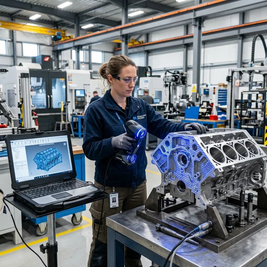
3D Laser Scanning
Capturing millions of data points from physical parts, massive assemblies, or full plant floors using high-precision LiDAR and structured light scanners.
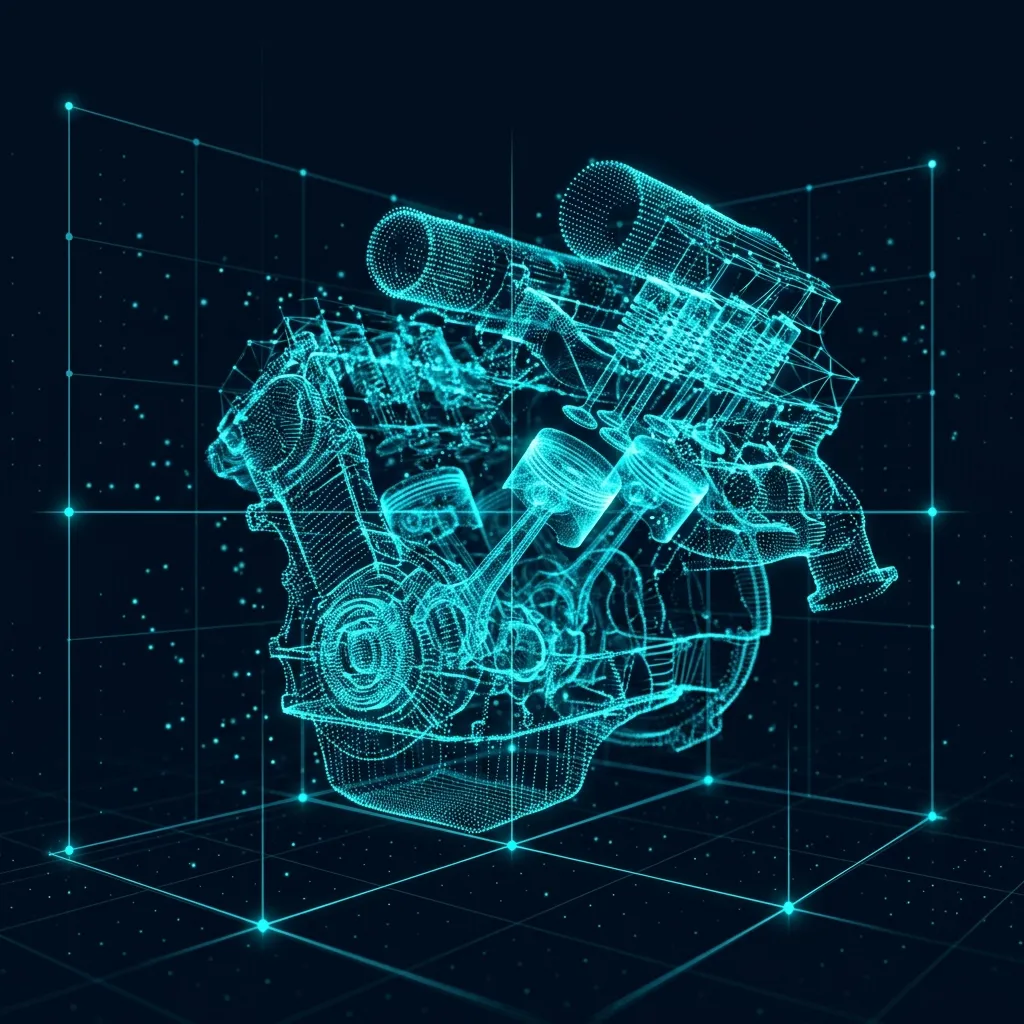
Point Cloud Processing
Cleaning, aligning, and registering the raw point cloud data into a unified, accurate spatial model ready for engineering extraction.

Geometry Extraction
Converting complex meshes into clean, editable parametric CAD models and identifying critical geometric features.

Draft Generation
Projecting the 3D model into 2D space, applying proper dimensioning schemes, datum references, and necessary section views.

Validation & QA
Rigorous cross-checking of the generated 2D drawings against the original 3D scan data to ensure sub-millimeter accuracy.
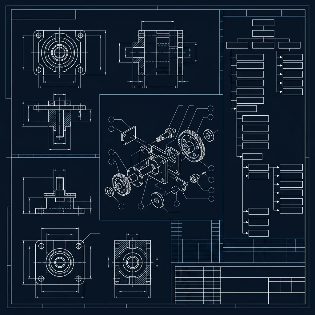
Production Documentation
Finalizing Title Blocks, BOMs, and exporting to standard formats (DWG, DXF, PDF) ready for the manufacturing floor.
The Manufacturing Drawing Lab
Deconstructing a true production-ready drawing blueprint for precision manufacturing.

Why Manufacturers Outsource to Us
Explore the dial below to see how our drawings support every department.
Hover a node on the dial
Discover the specific deliverables and engineering logic required at every stage.
Engineering Documentation Vault
The tangible assets you receive at the end of the process.
GD&T-Compliant Drawings
Assembly Models
Exploded View Packages
Shop Floor Prints
As-Built Documentation
BOM & Parts Lists
Legacy Conversion
DWG / DXF / PDF Files
What is 2D Drafting & Manufacturing Drawing Services India?
CAD Modeling and Drafting is the digital creation of parametric 3D solid models, sheet metal flat patterns, and 2D manufacturing blueprints with comprehensive GD&T callouts, datum schemes, and Bills of Materials (BOMs).
When to Select This Service
Choose parametric CAD drafting when converting legacy 2D drawings into native 3D solid models, detailing shop-floor blueprints per ASME Y14.5, or preparing tool-ready models for CNC machining and moulding.
Technical Capabilities & Verification Standards
Verified engineering parameters, hardware precision, and compliance benchmarks applied across all deliverables.
| Engineering Parameter | APJ 3D Capability & Precision Range | Compliance Standard / Verification |
|---|---|---|
| CAD Platforms | SolidWorks, Siemens NX, CATIA V5, Autodesk Inventor, Creo Parametric, AutoCAD | Native Feature Tree Formats |
| Drafting Standards | ASME Y14.5-2018, ISO 1101, ISO 128, DIN, JIS Standard Compliance | Full GD&T Tolerancing & Datums |
| Specialized Modeling | Class-A Surfacing, Complex Sheet Metal Flattening, Plastic Part Tooling DFM, Heavy Weldment Structures | Manufacturing-Ready Geometry |
| Drawing Deliverables | Fully Dimensioned 2D PDFs, DWG/DXF Flat Patterns, STEP AP242, Parasolid (.x_t), Native CAD Packages | Production-Ready Shop Blueprints |
| BOM & Documentation | Automated Hierarchical BOMs, Ballooned Assembly Drawings, Exploded Service Manuals, Hardware Catalogs | ERP-Ready Part Numbering |
| Quality Verification | Independent Senior Checker Review, Tolerance Stack-up Analysis, Interference & Clearance Checks | Zero-Defect Drafting Protocol |
| Turnaround Time | 24 to 72 hours for standard manufacturing drawing packages and CAD conversions | Scalable Dedicated Engineering Teams |
Frequently Asked Questions
Can you convert legacy 2D paper drawings or PDFs into 3D CAD models?
Can you convert legacy 2D paper drawings or PDFs into 3D CAD models?
Do your 2D engineering drawings include full GD&T callouts?
Do your 2D engineering drawings include full GD&T callouts?
How do you ensure sheet metal flat patterns account for bend allowances?
How do you ensure sheet metal flat patterns account for bend allowances?
Can you provide exploded views and assembly manuals for technical documentation?
Can you provide exploded views and assembly manuals for technical documentation?
What is the process for reviewing and revising drawing packages?
What is the process for reviewing and revising drawing packages?
Production-Ready Drawings Built for Manufacturing, Not Just Documentation
Transform legacy drawings, physical parts, and engineering concepts into clear, GD&T-compliant production documentation.