Lost Drawings
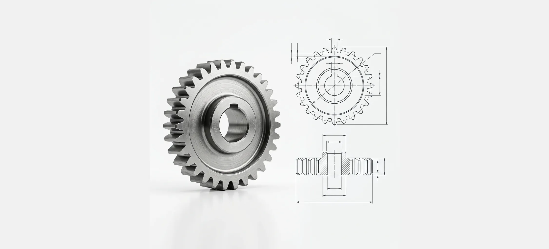
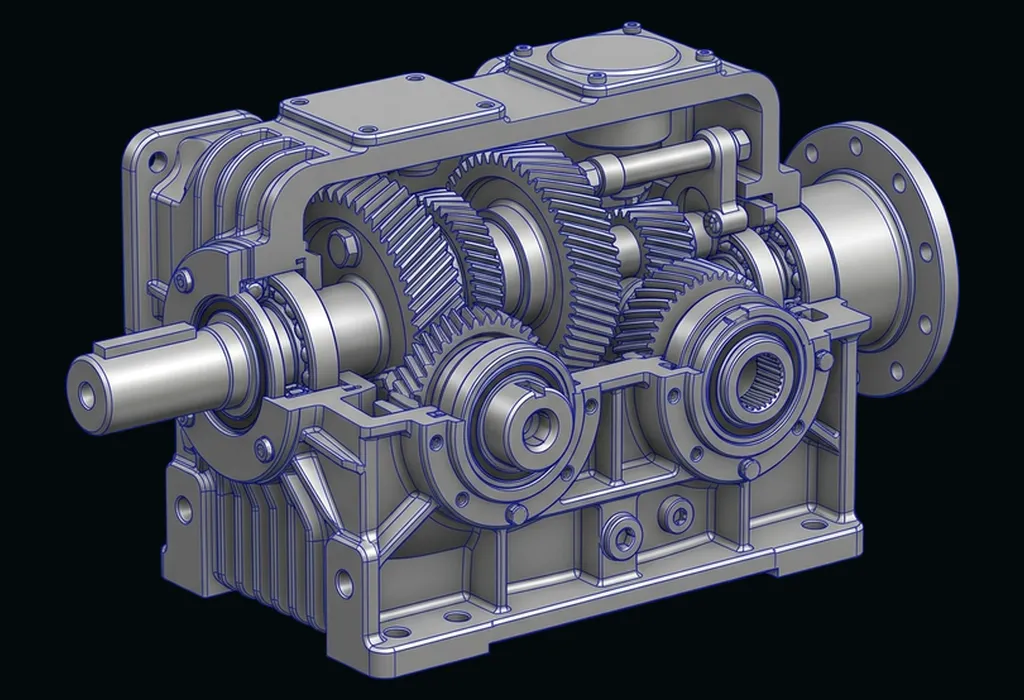
No digital data or prints available for legacy components. We extract complete geometric specifications directly from the physical component.
Reverse engineering is the process of digitizing an existing physical component -- one with no available drawings, CAD data, or digital record -- so it can be redesigned, replaced, or manufactured again. Instead of starting from a blank sheet, our engineers start from the part itself: a worn bearing housing, an obsolete casting, an imported machine element, or a shop-floor-modified tool.
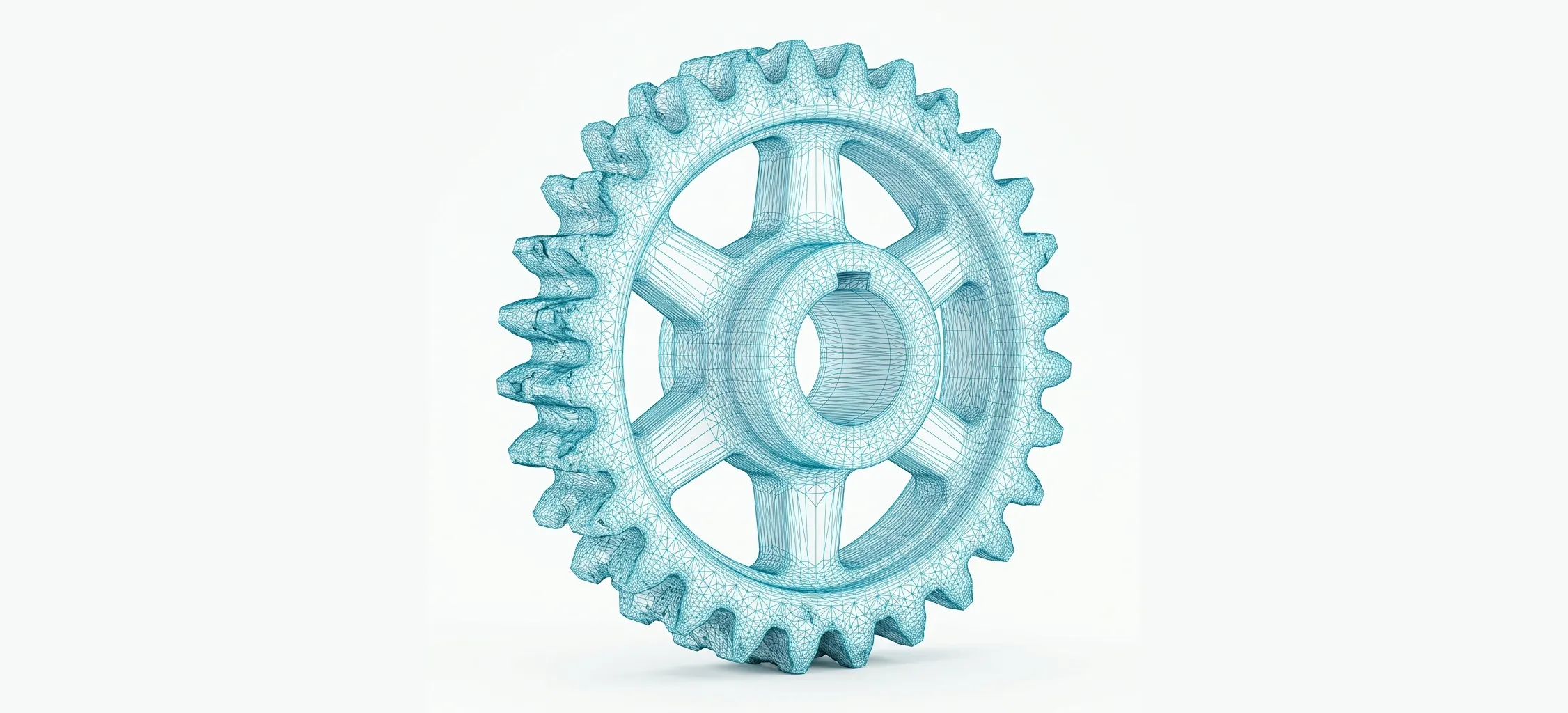
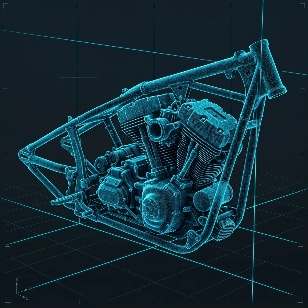
A structured-light or laser 3D scanner records millions of coordinate points across the part's surface, producing a dense point cloud or mesh that represents its true, as-built geometry -- including wear, distortion, or hand-fit modifications the original drawing never captured.
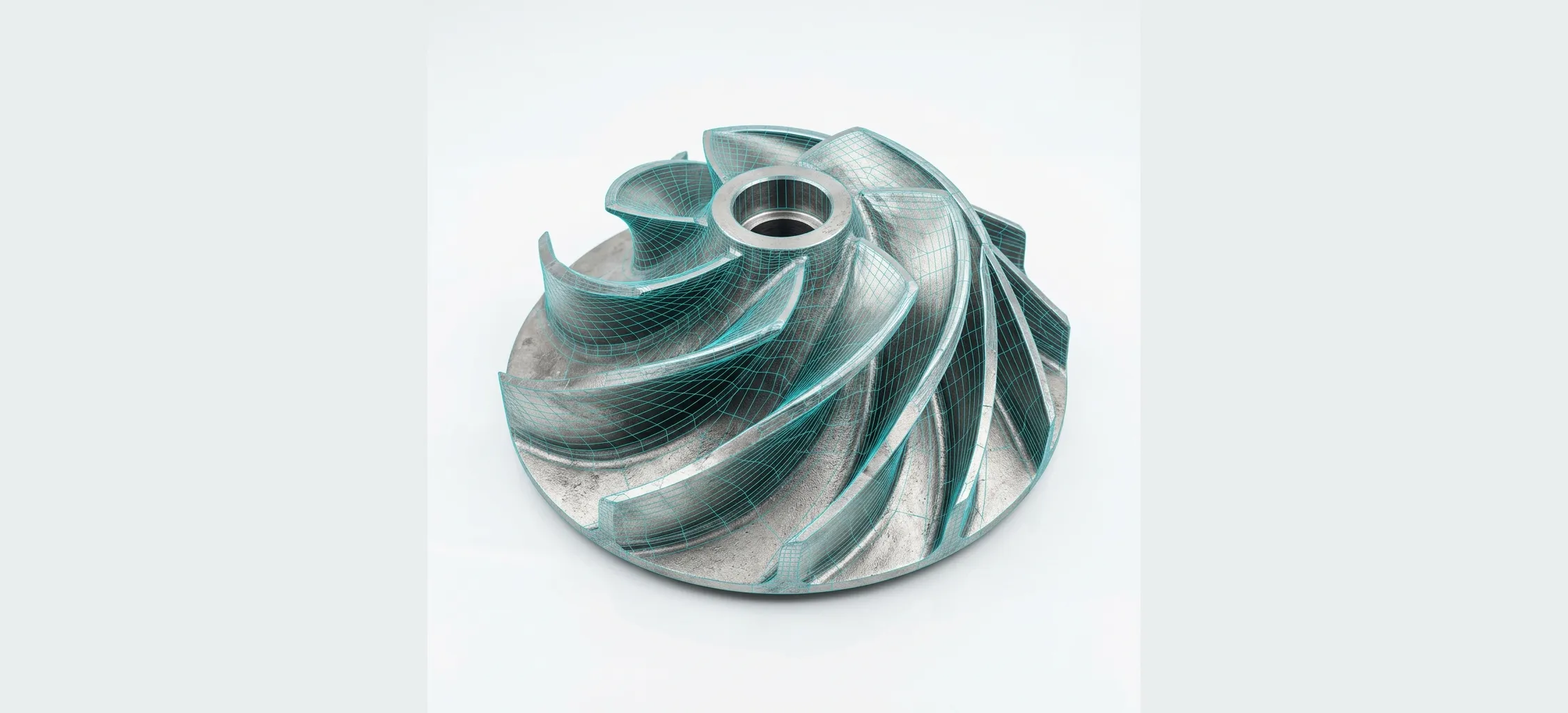
Engineers convert the raw mesh into a clean, parametric solid model in SolidWorks, Siemens NX, Creo, or CATIA -- separating functional features (bores, threads, mating faces) from organic surfaces so the result is fully editable, not just a frozen scan.
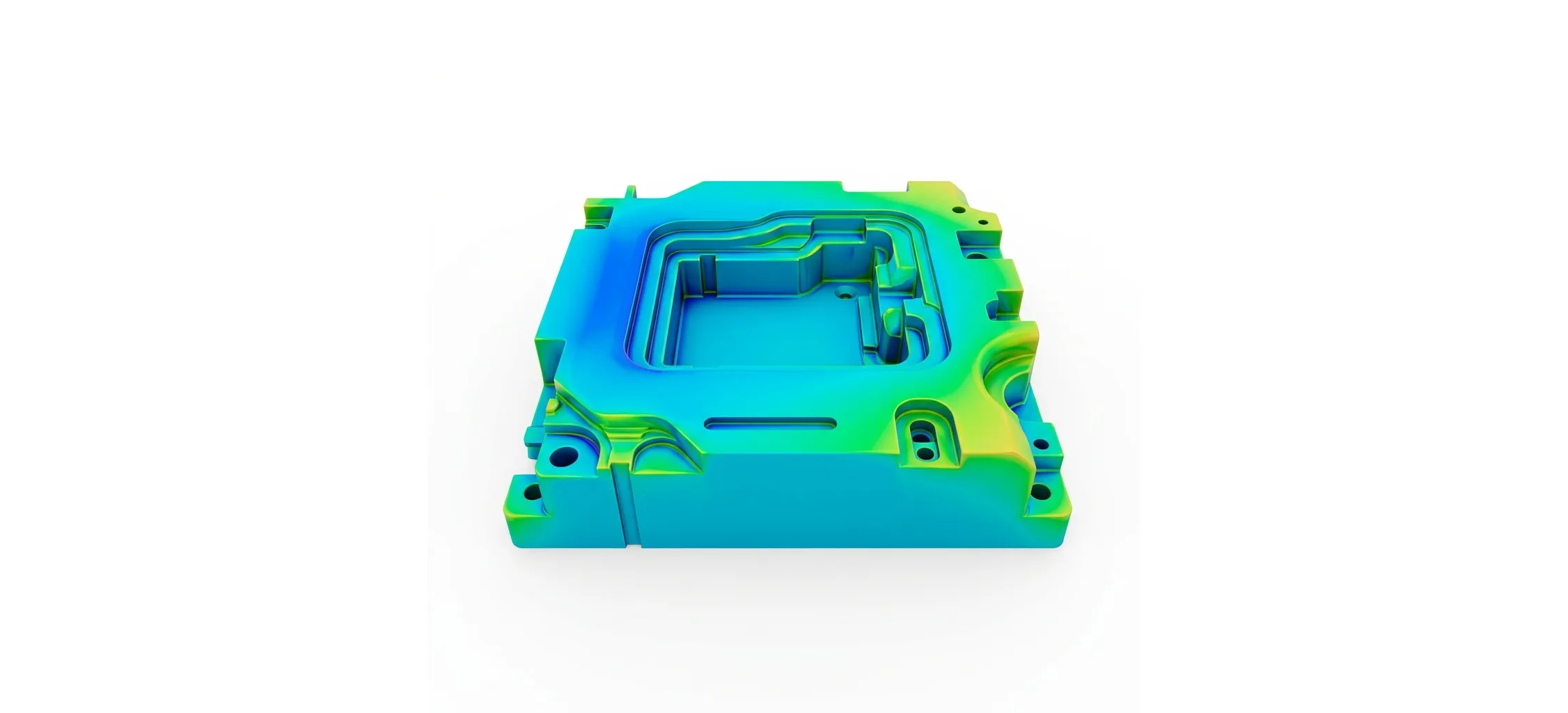
The reconstructed CAD is compared back against the original scan data to confirm dimensional accuracy, then issued with 2D manufacturing drawings and GD&T -- so the part can be re-manufactured, modified, or inspected with confidence.
No digital data or prints available for legacy components. We extract complete geometric specifications directly from the physical component.
Crucial machine elements are worn, damaged, or out of production. We rebuild the design to enable cost-effective regional replacements.
Expensive shipping cost and lead time for foreign components. Reverse engineering lets you manufacture high-precision equivalents locally.
Parts hand-tuned or modified on the shop floor during assembly. We scan the tool to document the modifications back into the master CAD.
We review the component geometry, critical tolerances, surface textures, and physical location to deploy the ideal coordinate capture configuration.
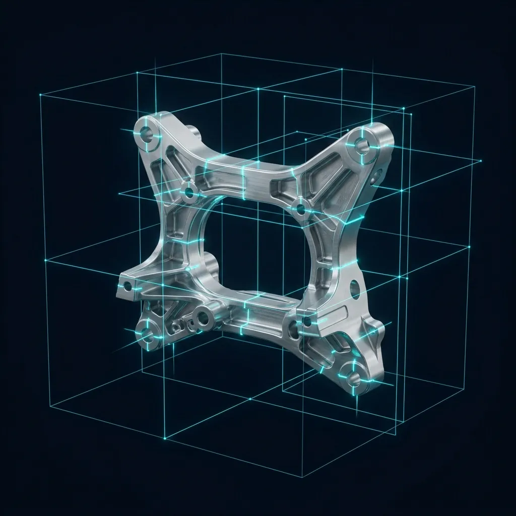
Deploying targeted tracking systems, we capture billions of dimensional points to compile a highly dense mesh file representing every contour of the part.

We transform unorganized mesh nodes into clean, parametric history trees. We separate organic structures from mechanical features to deliver editable solid files.

Every model is verified against the scan using deviation color maps. We confirm that target tolerances are satisfied before generating neutral export models.

Compare the raw 3D scan mesh with our reconstructed parametric CAD models. Select a component below to load the datasets inside the engineering viewport.
Complete digitization of a mid-size commuter vehicle. Scanned all structural connections, engine layout coordinates, and aerodynamic body contours to build a fully structured CAD assembly of 180+ parts for mechatronic packaging optimization.
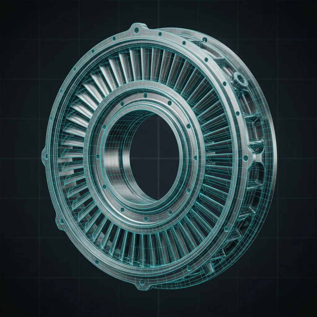
Reverse engineered a critical 1980s cooling rotor assembly lacking blueprints. Performed on-site HandySCAN blue light capturing, aligned data to fix local mechanical wear parameters, and supplied parametric SolidWorks models to recreate matching spares.
Performed high-precision scanning and deviation color map comparisons of structural components for aviation compliance. Met strict aeronautical safety margins with traceable dimensional accuracy documentation.
We fuse certified industrial metrology hardware with specialized engineering expertise to supply production-ready parametric datasets on tight timelines.
Get a custom quote in 24 hours.
We supply fully validated CAD models and traceable inspection reports with every reverse engineering project.
When a part exists but its CAD data doesn't, reverse engineering from a 3D scan is almost always faster and more accurate than a designer re-modeling the part from measurements and memory -- because the scan captures the real, as-built geometry rather than the designer's best guess at it.
Once the CAD model is rebuilt, it can be checked against manufactured parts through 3D inspection, or handed to production with a full BOM and parts list.
Reverse Engineering is the structured extraction of design intent from 3D scan data (point clouds/meshes) to rebuild fully editable, parametric 3D CAD models and production drawings for legacy, obsolete, or undocumented parts.
Choose reverse engineering when replacing obsolete machinery components with no existing drawings, recreating worn tooling and stamping dies, benchmarking competitor hardware, or redesigning aftermarket automotive accessories.
Verified engineering parameters, hardware precision, and compliance benchmarks applied across all deliverables.
| Engineering Parameter | APJ 3D Capability & Precision Range | Compliance Standard / Verification |
|---|---|---|
| Reconstruction Techniques | Parametric Feature Modeling, Hybrid Surface-Solid Modeling, Class-A B-Rep Surfacing | Design Intent Extraction |
| Scan-to-CAD Deviation | Surface deviation within ±0.025 mm to ±0.050 mm of scan data (Geometry dependent) | Geomagic Design X / Geomagic Control X |
| Supported Part Types | Castings, forgings, stampings, injection molded plastics, turbine blades, automotive body panels, tooling dies | Micron to Multi-Meter Scale |
| Output Formats | Native SolidWorks (.sldprt), Siemens NX (.prt), CATIA (.CATPart), STEP (.stp), IGES (.igs), Parasolid (.x_t) | Fully Editable Feature Trees |
| Manufacturing Detailing | Draft angle optimization, wall thickness regularization, fillet reconstruction, GD&T 2D blueprints | DFM / Tooling Ready |
| Quality Assurance | 3D Color Map Scan-to-CAD overlay deviation report verifying geometric fidelity | 100% Deviation Inspected |
| Turnaround Time | 2 to 5 business days for standard complex mechanical components and assemblies | Pan-India On-Site 3D Scanning Available |
Upload your component details and receive a realistic reverse engineering plan, delivery timeline, and CAD reconstruction strategy from APJ 3D's dedicated reverse engineering team.