Manufacturing Risk Points
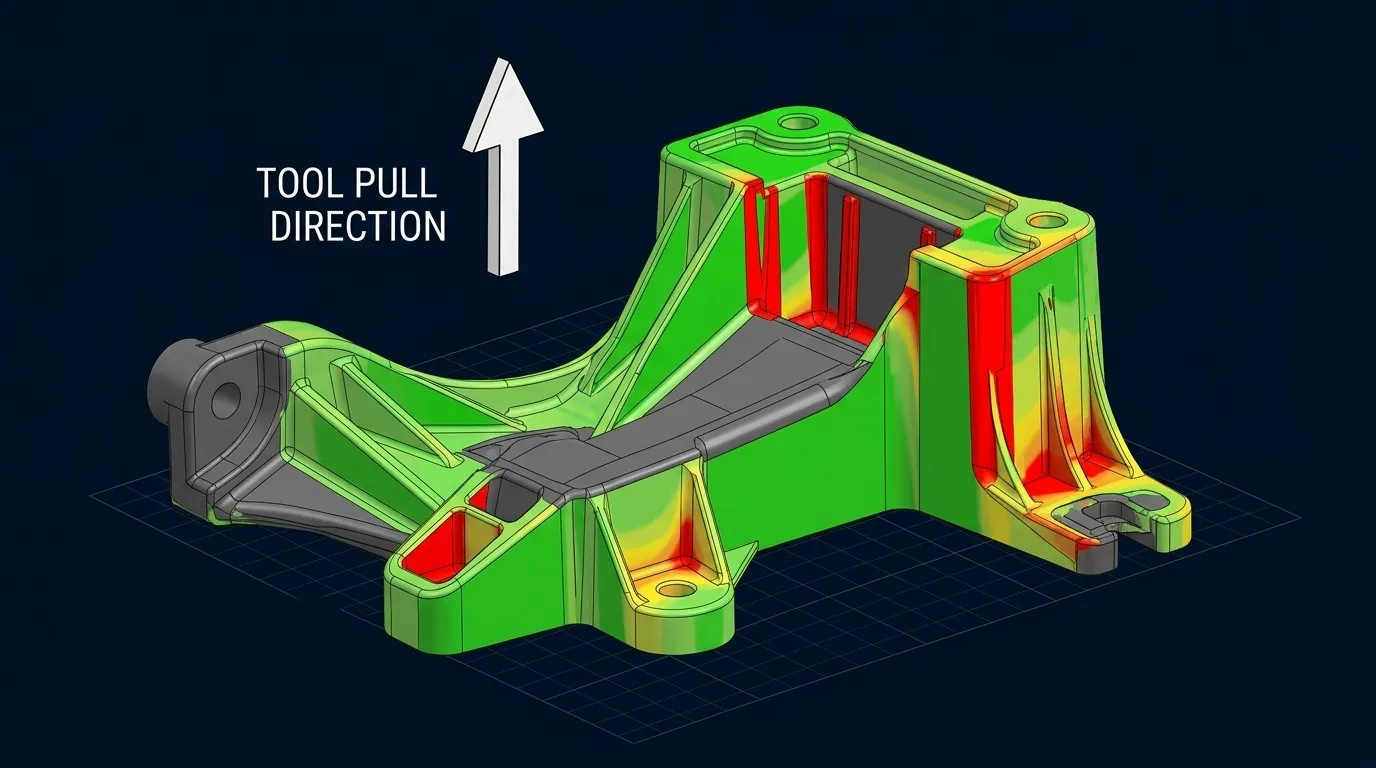
Draft Angles
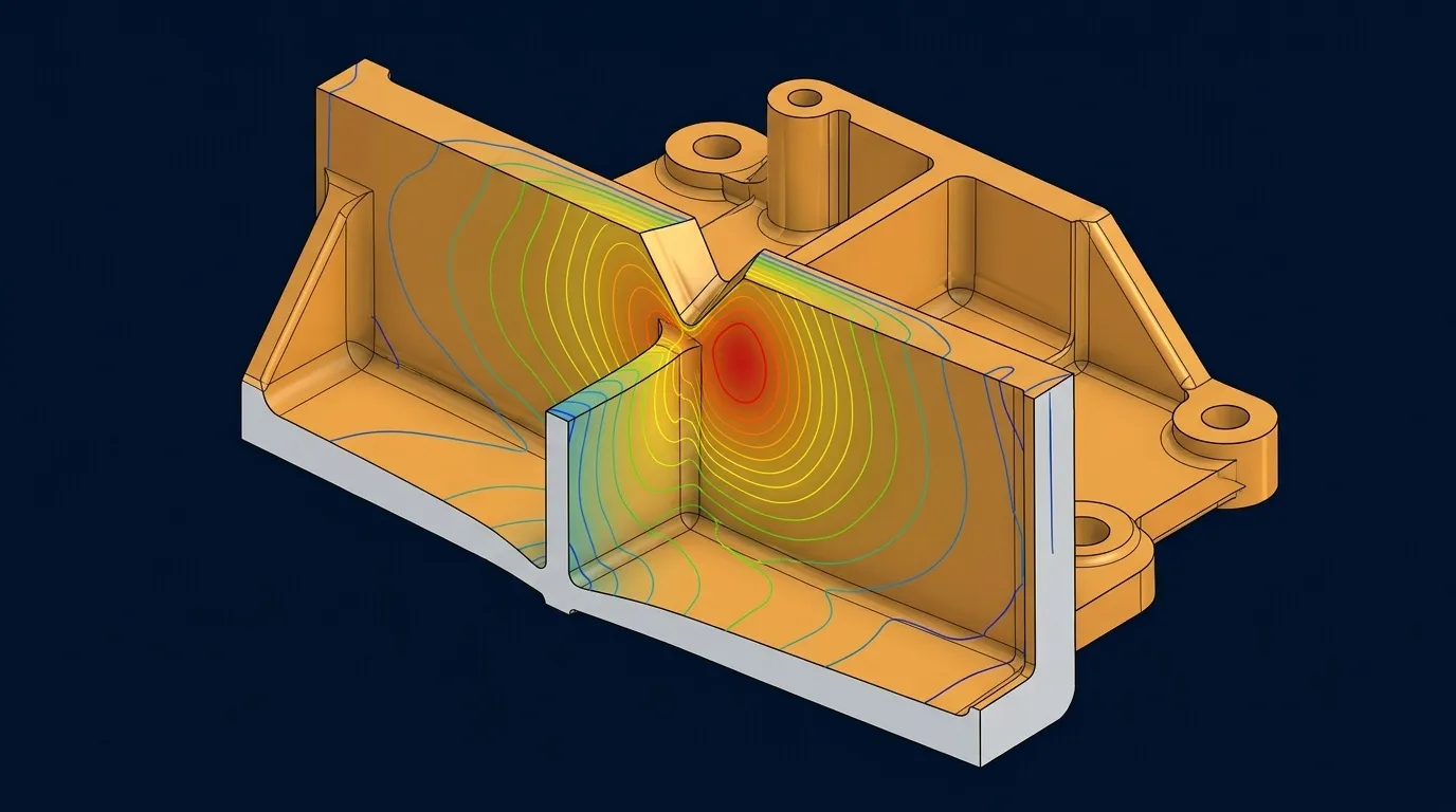
Sink Marks
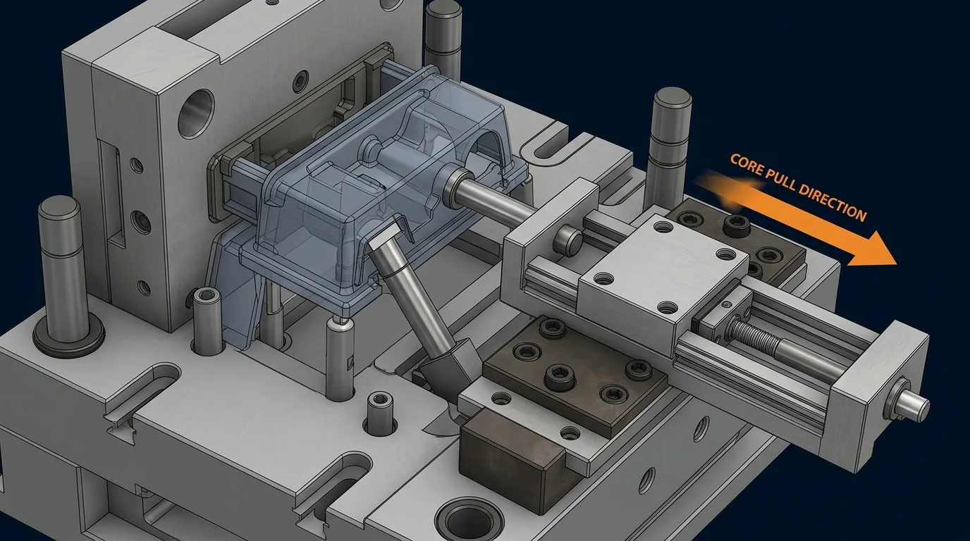
Undercuts
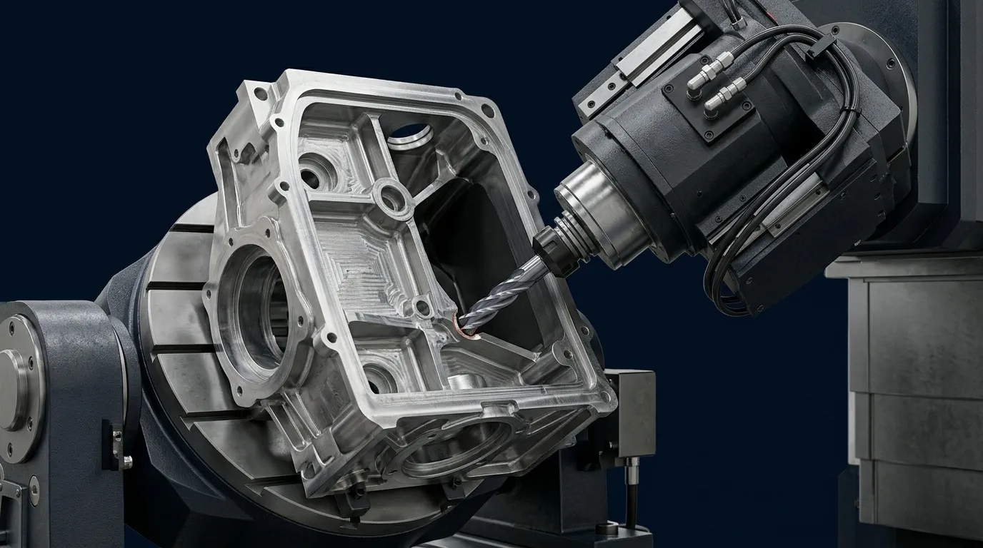
Tool Access
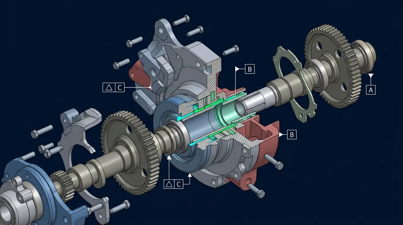
Assembly Clash
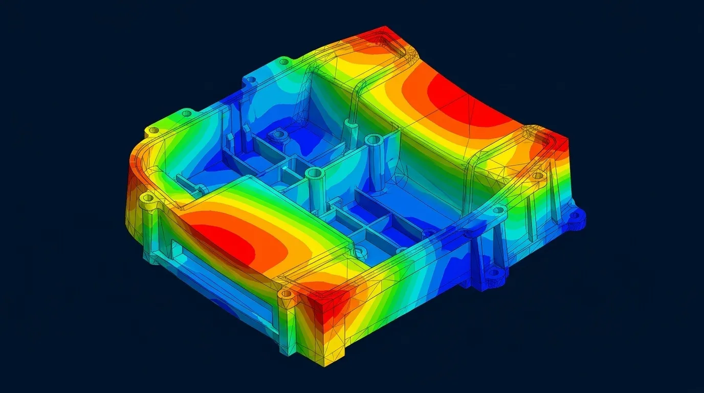
Warpage
Manufacturing Process Verification
Hover over the holographic data slabs to deploy the specialized DFM checklists for your targeted production domain.
Moulding
- ✓ Draft Angle Analysis
- ✓ Rib vs Wall Ratio
- ✓ Boss Integrity Check
- ✓ Parting Line Topology
- ✓ Sink Mark Prediction
- ✓ Undercut Solutions
Metal
- ✓ Min Bend Radii limits
- ✓ Hole-to-Edge Offset
- ✓ Flange Relief Cuts
- ✓ Weld Accessibility
- ✓ Burr Clearances
- ✓ Flat Pattern Validation
Forging
- ✓ Parting Plane Setup
- ✓ Shrinkage Allowances
- ✓ Thermal Hot Spots
- ✓ Core Pull Directions
- ✓ Machining Datums
- ✓ Wall Transitions
Machining
- ✓ Tool Reach Checks
- ✓ Pocket Corner Radii
- ✓ Cavity Aspect Ratios
- ✓ Fixturing Strategy
- ✓ Tap Accessibility
- ✓ Setup Reduction
What Our DFM Dashboard Detects
Every CAD file is subjected to an exhaustive 360° topology sweep. Hover the sensory nodes to inspect the critical geometry heuristics mapped by our engine.
Per-face draft validation against mould pull direction & shrinkage.
Min/max thickness heat-mapping across the full envelope.
Machining reach & cutter clearance bounding box simulation.
Thermal gradient and mass concentration hotspot detection.
Rib-to-wall thickness mathematics to prevent surface sink marks.
Blind hole, internal geometry, and slide-requiring undercut flagging.
Multi-axis operational sequence and fixturing vector analysis.
Mating interference, GD&T conflict, and insertion path mapping.
Before vs After DFM Assessment
Toggle the system overlay below to witness the algorithmic impact of our DFM engineering review on production cost, quality, and cycle time.
Unoptimised Baseline
Raw engineering model direct from design team. High risk of tool collision, material warp, and inflated BOM cost.
DFM Certified Model
APJ 3D validated geometry. Drafts corrected, kinematics aligned, and tool paths streamlined for immediate production scale.
From CAD to Manufacturing Sign-Off
A stringent, engineering-led pipeline delivering decisive redesign recommendations and absolute production certainty.
Data Intake & Security
Secure, NDA-protected ingestion of native engineering files (STEP, IGES, Parasolid). Design intent established.
Automated Topography Scan
Heuristic algorithms map wall thickness derivations, draft angle absences, and undercut interferences across the envelope.
Domain-Specific Analysis
Engineers cross-reference geometric flags against targeted manufacturing parameters classifying severity.
Redesign Synthesis
Actionable engineering resolutions formulated. Alternative topologies modelled to circumvent failure modes.
Report Compilation
Structured delivery of the DFM dossier containing annotated CAD screenshots, issue logs, and redesign roadmaps.
Manufacturing Sign-Off
Post-revision secondary review resulting in the issuance of an APJ 3D DFM Certificate—authorizing procurement.
What is DFM Assessment Services India?
Design for Manufacturing (DFM) Assessment is a manufacturability review of CAD geometry that detects critical design flaws — draft angles, wall thickness inconsistencies, and tooling conflicts — before the first tool is cut, preventing costly downstream rework.
When to Select This Service
Choose DFM assessment when you need to eliminate manufacturing surprises before tooling investment, validate draft angles and wall thickness at the CAD stage, or benchmark a design's manufacturability ahead of production.
Technical Capabilities & Verification Standards
Verified engineering parameters, hardware precision, and compliance benchmarks applied across all deliverables.
| Engineering Parameter | APJ 3D Capability & Precision Range | Compliance Standard / Verification |
|---|---|---|
| Draft Angle Analysis | CAD geometry is scanned for zero-draft and negative-draft faces that would prevent clean mould release | Injection Moulding DFM Checklist |
| Rib-to-Wall Ratio | Internal rib thickness is checked against the adjacent nominal wall, flagging ribs exceeding 60% of wall thickness | Sink Mark Prediction |
| Undercut & Side-Core Assessment | Blind holes and undercut features requiring slides or side-action cores are flagged, with straight-pull alternatives recommended | Tooling Complexity Rating (Low / Medium / High) |
| Parting Line & Gate Review | Parting line topology and wall-thickness uniformity are reviewed, with gate location optimized via mould-fill simulation | Injection Moulding & Sheet Metal DFM |
| Manufacturability Scoring | Each CAD submission is scored on a 0-100 manufacturability scale and marked Approved or Not Approved for tooling | Manufacturability Score Report |
| Production Domain Coverage | Dedicated DFM checklists applied across Injection Moulding and Sheet Metal production domains | Domain-Specific Checklist |
Frequently Asked Questions
Can you perform 3D scanning on-site at our manufacturing plant?
Can you perform 3D scanning on-site at our manufacturing plant?
How do 3D scanning and reverse engineering differ?
How do 3D scanning and reverse engineering differ?
What is a color deviation inspection map?
What is a color deviation inspection map?
Can dark, shiny, or transparent surfaces be scanned?
Can dark, shiny, or transparent surfaces be scanned?
What accuracy can we expect for automotive and aerospace components?
What accuracy can we expect for automotive and aerospace components?
Design Better. Manufacture Faster.
Our DFM Assessment Services and Design for Manufacturing Analysis eliminate production failures before a single tool is cut. Partner with APJ 3D for definitive Manufacturability Assessment Engineering — from CAD review to full Product DFM Benchmarking Services — and deliver components engineered to manufacture, right first time.