DIGITAL ENGINEERING WORKFLOW INDIA

Digital Engineering Workflow
Connected Systems

APJ 3D orchestrates end-to-end Digital Engineering Workflow India ecosystems, uniting 3D scanning, parametric CAD modeling, finite element simulation, and automated inspection. Our connected engineering architecture guarantees complete digital continuity, eliminating design silos and accelerating time-to-market.

Zero Data Drop Bi-Directional CAD-CAE Enterprise PLM Sync

Where Workflows Break vs Connect

Interactive Before vs After comparison contrasting siloed manual handoffs against an automated digital thread.

Broken Legacy Silo HIGH REWORK RISK
  • Manual geometry translation stripping parametric assembly trees.
  • Simulation feedback documented in static Excel sheets and unread emails.
  • Designers accidentally modifying outdated CAD revision branches.
  • Zero automated traceability between physical test bench and FEA assumptions.
Result: 40% engineering delay and costly late tooling revisions.
Connected APJ Digital Thread PROVEN 10X ROI
  • Direct associative sync maintaining CATIA/NX feature parameters.
  • Automated solver feedback embedded directly into PLM decision gates.
  • Single source of truth locking revision control across all engineering seats.
  • Closed-loop correlation linking real-world data directly to simulation scripts.
Result: Zero version mismatch and rapid sign-off across 4,000+ tasks.
Connected vs Broken Engineering Workflow Comparison Graphic

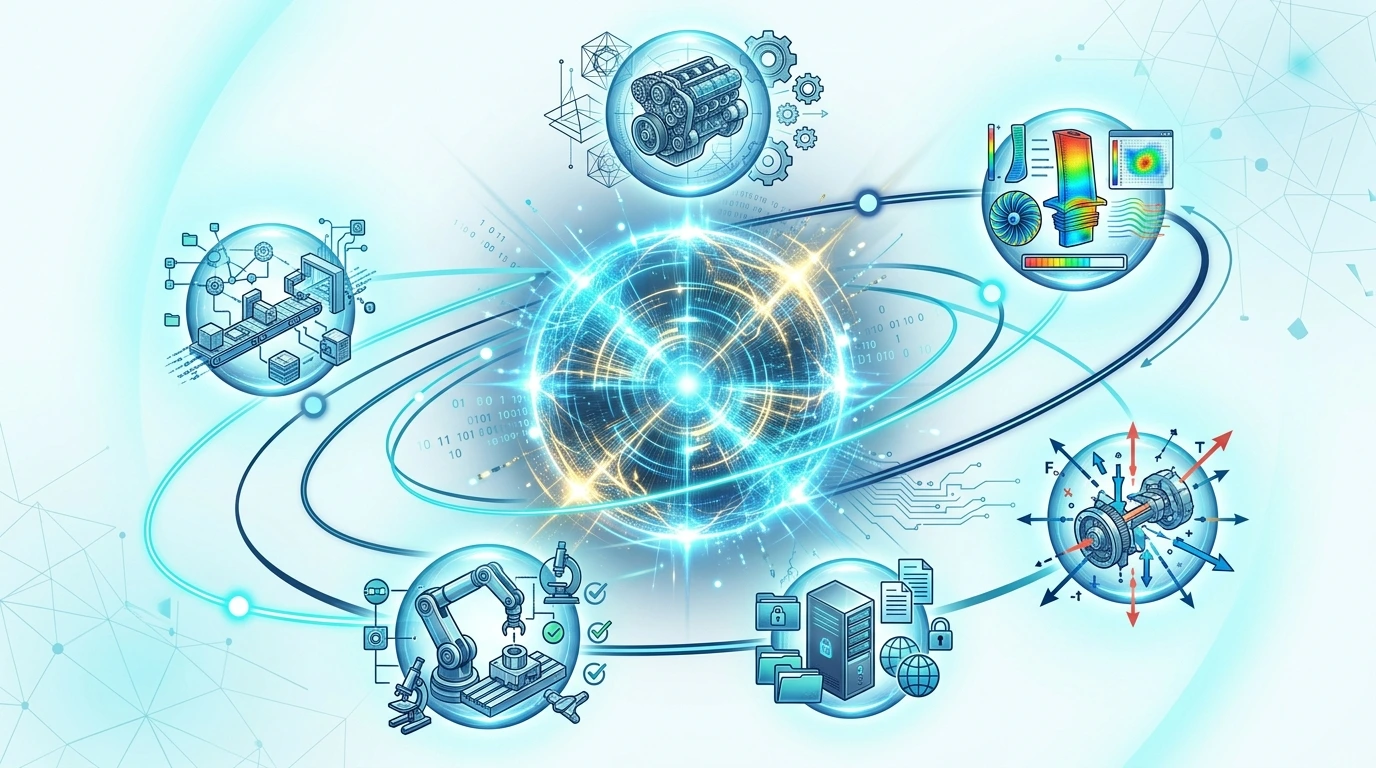
Radial Digital Thread Architecture

Orbiting engineering satellites feeding synchronized intelligence into the central decision nucleus.

1. CAE Digital Thread
2. CAD Revision
3. Load Cases
4. Result Vault
5. Design Review
6. PLM Record
ACTIVE SATELLITE FOCUS:

CAE Digital Thread Setup

Expands bi-directional connectivity between CAD geometry vaults and automated ANSYS solver scripts.

Powering premier Engineering Simulation Workflow India and CAE Digital Thread Setup.
Radial Digital Thread Architecture with Central Nucleus and Satellite Engineering Nodes

Milestone Roadmap Drawer

Interactive horizontal timeline expanding into detailed deliverable and software execution drawers.

1. Requirements
2. CAD Extract
3. Solver Sweep
4. Design Review
5. PLM Release

Milestone 1: Requirements & Load Envelope

Deliverable: Standardized operational multi-physics boundary condition document.
Software: Engineering Load Case Matrix & APJ Protocol Setup.
5-Stage Digital Engineering Workflow Milestone Dashboard

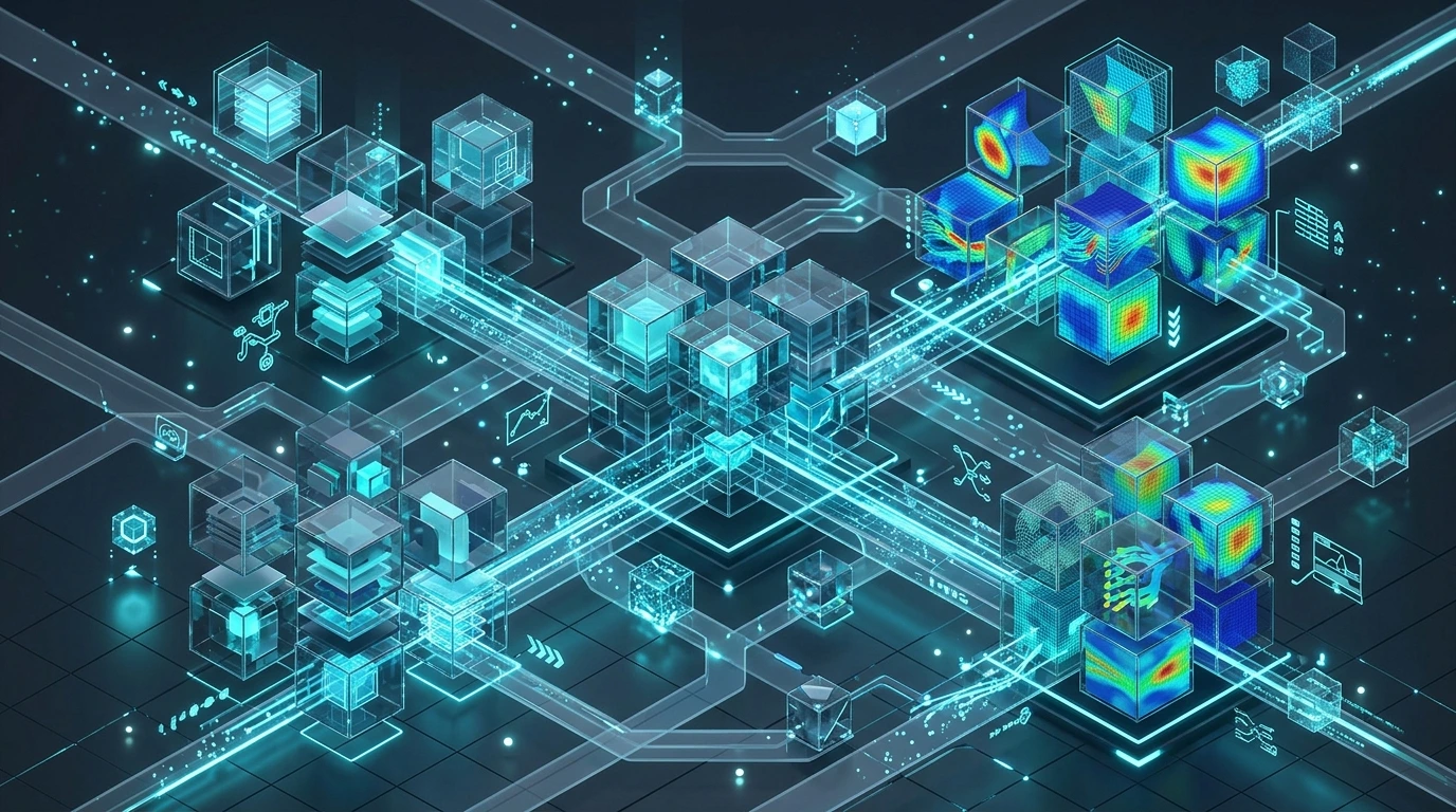
Floating Glass Ecosystem Hub

Interconnected software network linking premier CAD platforms directly to multi-physics solvers and PLM archives.

CAD SOURCE

CATIA / NX / SolidWorks

Parametric Master Models

CAE CORE

HyperMesh / ANSYS

Multi-Physics Simulation

ENTERPRISE PLM

PLM Vault Sync

Traceable Digital Records

CATIA V5 & Siemens NX Native Sync

Data Flow: Associative 3D solid and surface feature trees transferred without STEP conversion loss.

CAD-CAE-PLM Integration Glass Cube Ecosystem

Project Delivery Notebook Storyboard

Interactive engineering notebook pages documenting a real-world digital workflow transformation.

STAGE 01 Workflow Audit & Diagnosis
STAGE 02 Protocol Setup & Scripting
STAGE 03 Bi-Directional Loop Execution
NOTEBOOK ENTRY READOUT:
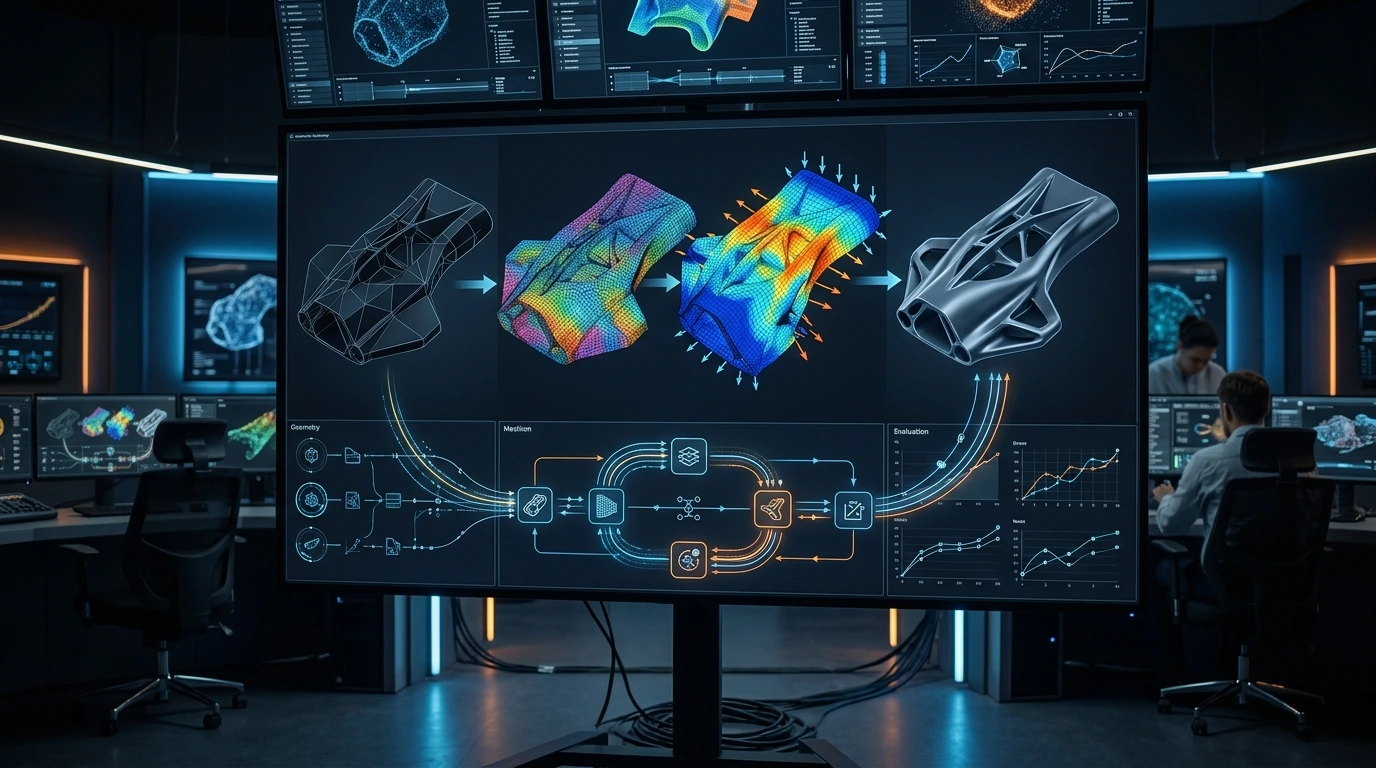
Page 01: Workflow Audit & Bottleneck Identification

Audit revealed 35% time wasted in manual CAD-to-CAE geometry clean-up and email file transfers.
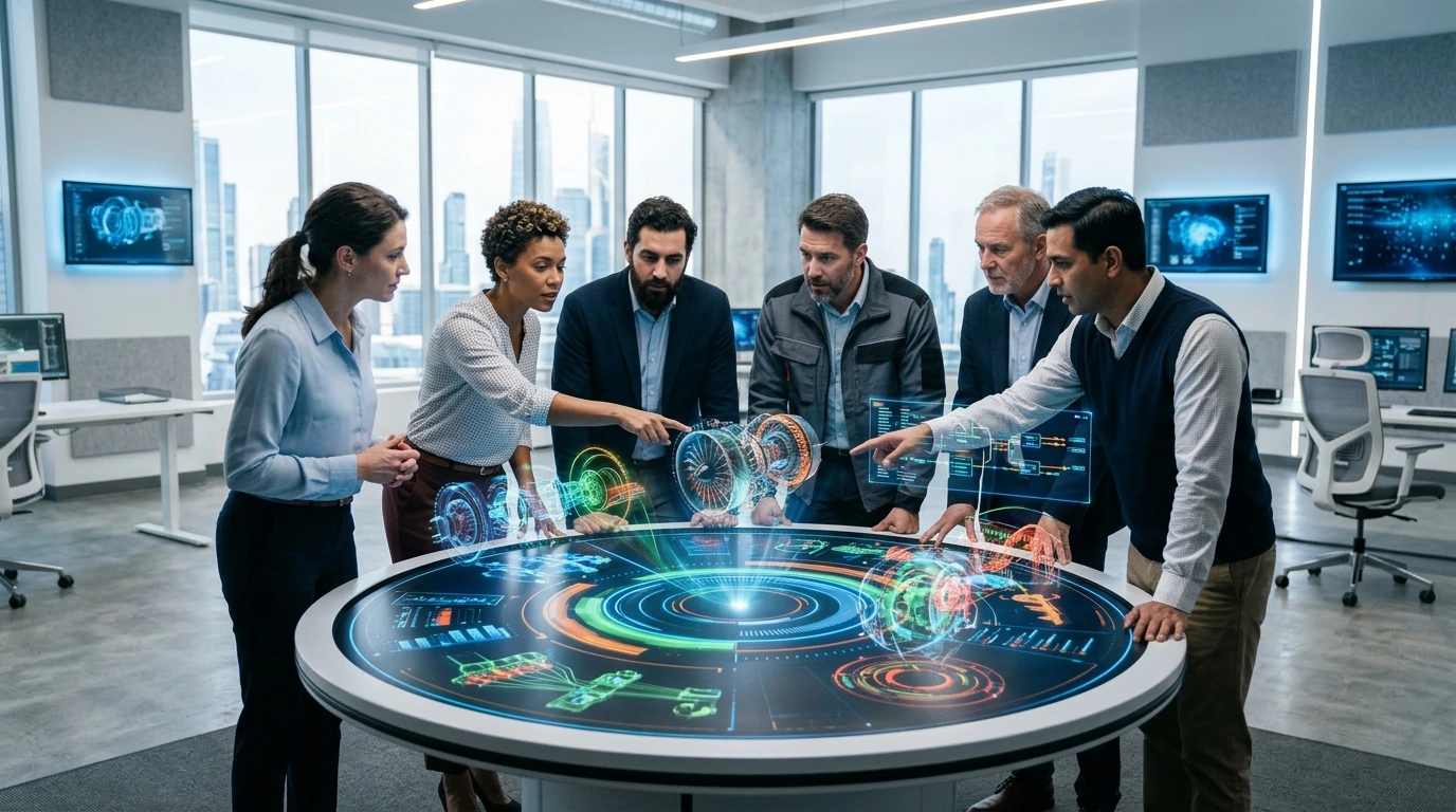
Engineer Reviewing CAD Revisions with Simulation Dashboard

Engineering Team Network Tree

Empowering cross-functional engineering stakeholders across the digital product development lifecycle.

Engineering Directors Executive Governance
CAE Simulation Leads Solver Automation
CAD Design Engineers Associative Guidance
PLM Enterprise Leads Digital Twin Archive
Engineering Directors & VPs

Benefit: Enterprise visibility, predictable project schedules, and 10x ROI across NPD portfolios.

Cross-Functional Engineering Collaboration around Holographic Table
Technical Service Overview Reviewed by APJ 3D Engineering Desk • Updated September 2026

What is Digital Engineering Workflow India?

A Digital Engineering Workflow is a connected engineering architecture that unites 3D scanning, parametric CAD modeling, finite element simulation, and automated inspection into a single continuous data pipeline, eliminating design silos between disciplines.

When to Select This Service

Choose a digital engineering workflow engagement when disconnected tools and manual handoffs are slowing your program, or when you need end-to-end digital continuity from scan data through simulation and inspection to accelerate time-to-market.

Digital Engineering Workflow India Technical Specifications

Technical Capabilities & Verification Standards

Verified engineering parameters, hardware precision, and compliance benchmarks applied across all deliverables.

Engineering Parameter APJ 3D Capability & Precision Range Compliance Standard / Verification
CAE Digital Thread Setup Bi-directional connectivity linking CAD geometry vaults directly to automated ANSYS solver scripts Digital Thread Architecture
Bi-Directional CAD-CAE Loop Solver outputs are linked directly to native CAD variables, achieving up to 4x faster design iteration Closed-Loop Correlation
PLM Vault Integration Certified production data and sign-off certificates synced directly into Teamcenter or Windchill PLM repositories Enterprise PLM Sync
Revision Control Single source of truth locking revision control across all engineering seats on the program Closed-Loop Data Governance
Design Review Milestone Collaborative trade-off decision log comparing mass versus stiffness feeds a joint design review gate Milestone-Based Workflow
Workflow Stages Structured staged progression from CAD geometry and solver setup through bi-directional loop execution to PLM release Staged Digital Thread Process
FAQ

Frequently Asked Questions

Can you perform 3D scanning on-site at our manufacturing plant?

Yes. Our engineers travel across India with portable HandySCAN 3D, optical CMMs, and laser trackers to scan parts, dies, tooling, and vehicle bodies directly on your shop floor without disassembly.

How do 3D scanning and reverse engineering differ?

3D scanning captures the raw physical surface geometry as a dense polygonal mesh (.STL). Reverse engineering takes that scan mesh and reconstructs a fully parametric, editable 3D CAD model (STEP, IGES, SolidWorks, NX) with design intent and standard geometric features.

What is a color deviation inspection map?

A color deviation map is a 3D visual comparison of the scanned physical part overlaid against the nominal CAD model. Color gradients (green = in tolerance, red = excess material, blue = undersize) immediately highlight manufacturing warpage, shrinkage, or machining errors.

Can dark, shiny, or transparent surfaces be scanned?

Yes. Our blue laser and structured light scanners handle dark and metallic surfaces directly. For highly reflective chrome or clear glass, a temporary sublimating scan spray is applied that evaporates completely without residue.

What accuracy can we expect for automotive and aerospace components?

We achieve volumetric accuracy down to 0.020 mm to 0.040 mm depending on part size and sensor setup, fully verified against VDI/VDE 2634 and ISO 10360 metrology standards.

Build a Connected Workflow That Keeps CAD, Simulation, and Decisions in Sync

Architect an unbroken Digital Engineering Workflow India pipeline. Enable premier CAE Digital Thread Setup and seamless PLM Simulation Integration India across your engineering ecosystem.