Simulation vs Physical
Validation Strategy
Closing the gap between virtual FEA predictions and real-world laboratory strain gauge measurements. APJ 3D delivers rigorous Simulation Physical Correlation India and structured CAE Test Correlation Service across automotive, aerospace, and defense manufacturing.
Why Simulation & Testing Disagree
Interactive comparison wall isolating the root causes of discrepancy between virtual models and physical test labs.
Higher Stiffness (Lower Deflection)
Calibration: Modeling non-linear bolt pre-load and test fixture compliance rather than rigid constraints.
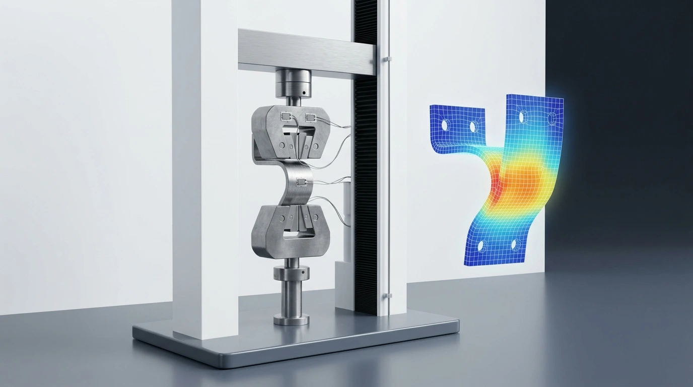
CAE Test Correlation Workflow
Vertical sequential engineering pipeline aligning raw test lab data with finite element solvers.
Stage 01: Test Data Audit & Cleansing
Audit raw strain gauge, accelerometer, and thermocouple logs to filter electrical noise and drift.
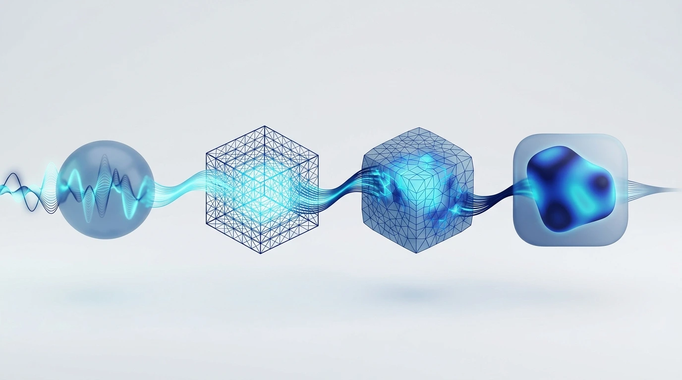
Correlation Investigation Dashboard
Expandable engineering diagnostic modules troubleshooting complex multi-physics discrepancies.
Boundary Conditions
Animated Support Fixture CheckMaterial Models
Material Database AnimationMatched Location Check
Sensor Co-Location SyncMesh & Solver Check
Hex Mesh Refinement Sweep1. Boundary Conditions Diagnostics
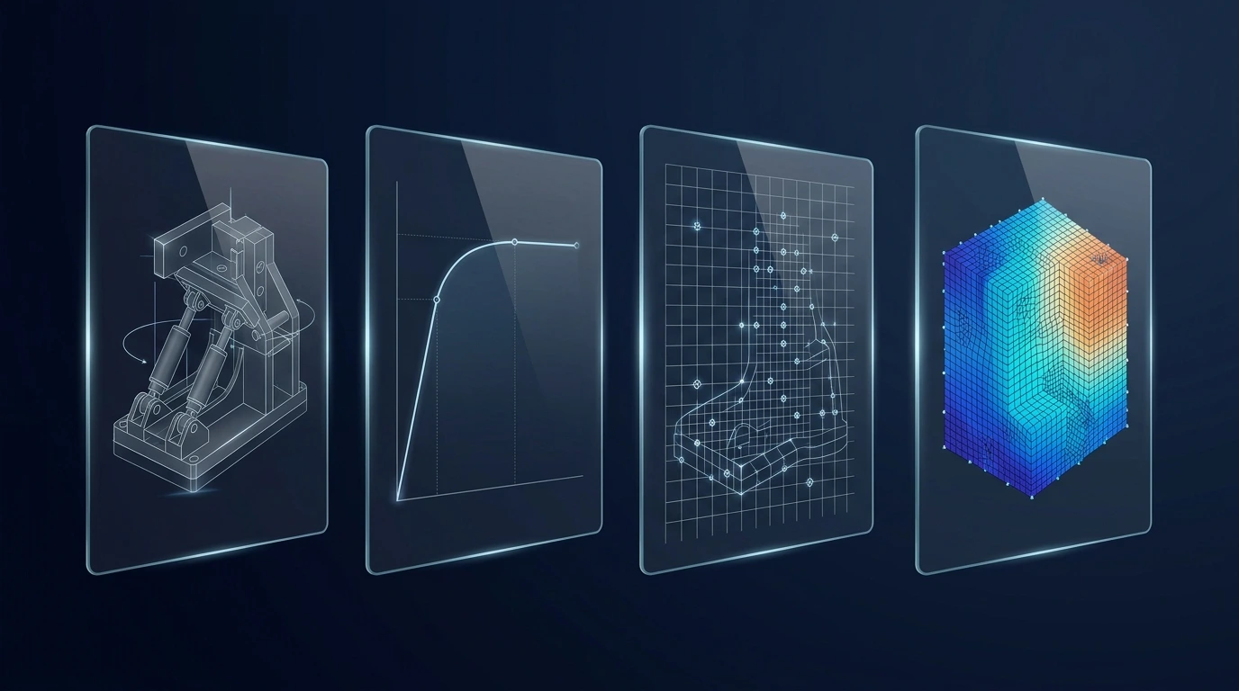
Accuracy Band Visualizer
Defining acceptable accuracy bands first to prevent endless solver iterations and ensure confident sign-off.
Stress Contour Target: ±5% Agreement
Target Accuracy: Von Mises stress peaks matched within 5% against 3-axis rosette strain gauge grids.

Real Correlation Case Study
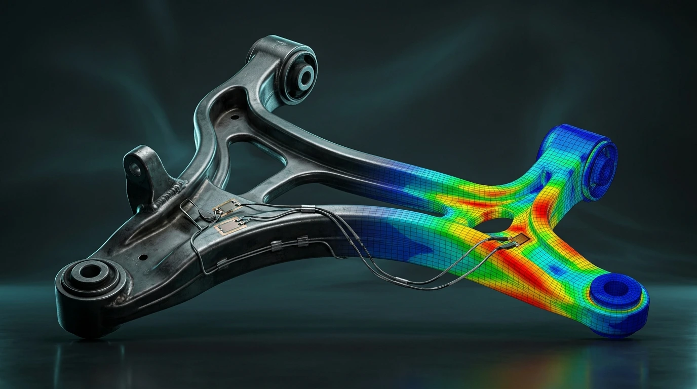
Interactive engineering notebook tracking the correlation resolution of a high-load automotive suspension arm.
Step 1: Problem Statement & Initial Gap
Initial FEA predicted 210 MPa peak stress, but laboratory strain gauge recorded 248 MPa (18% discrepancy).
Industries & Engineering Teams Network
Connected validation nodes empowering OEM test labs, CAE teams, and R&D leaders across India.
Validation Problem: Chassis fatigue life correlation against 4-poster road simulator rigs.
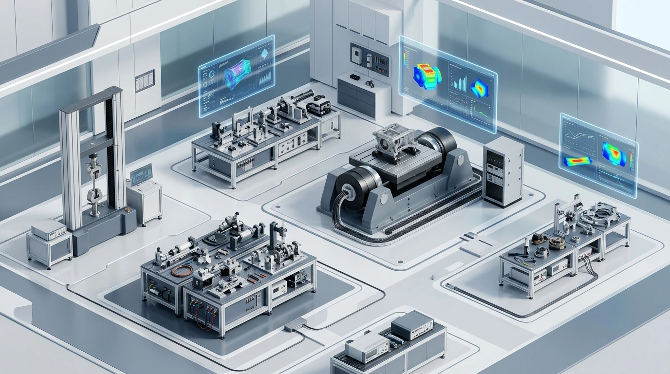
What is Simulation vs Physical Validation Strategy India — APJ 3D?
CAE Simulation (FEA & CFD) is the numerical modeling of physical systems to predict structural stress, thermal dissipation, fluid flow, crashworthiness, and dynamic fatigue life under real-world operational loads.
When to Select This Service
Choose CAE simulation during early product development to virtually validate design integrity, optimize part weight, verify safety factors, and eliminate physical prototype failure risks before committing to production tooling.
Technical Capabilities & Verification Standards
Verified engineering parameters, hardware precision, and compliance benchmarks applied across all deliverables.
| Engineering Parameter | APJ 3D Capability & Precision Range | Compliance Standard / Verification |
|---|---|---|
| Simulation Disciplines | Linear/Non-Linear Structural FEA, Thermal Analysis, CFD Fluid Dynamics, Crash & Impact, Fatigue & Durability, NVH | ISO 9001 / NAFEMS Validated Procedures |
| Solvers & Software | ANSYS Mechanical, Abaqus, Altair HyperWorks/OptiStruct, Moldflow, OpenFOAM, LS-DYNA | High-Performance Computing (HPC) Clusters |
| Material Models | Elastic-Plastic metals, Hyperelastic rubbers, Composites, Viscoelastic polymers, Temperature-dependent curves | Tested Material Property Databases |
| Mould Flow Capabilities | Fill time, injection pressure, weld line prediction, sink marks, cooling circuit efficiency, volumetric shrinkage & warpage | Autodesk Moldflow Insight Validated |
| Deliverables | Comprehensive Engineering Reports, Von Mises Stress Plots, Factor of Safety (FoS) Maps, Deformation Animations, Optimization STEPs | Actionable Design Recommendation Summaries |
| Model Scale | From precision micromixers and plastic clips up to full vehicle chassis and industrial equipment weldments | Multi-Million Degree-of-Freedom Meshes |
| Turnaround Time | 3 to 7 business days for standard FEA/CFD studies; 24–48h for urgent gate location & fill checks | Dedicated Senior CAE Analysts |
Frequently Asked Questions
What information is required to start an FEA or CFD simulation?
What information is required to start an FEA or CFD simulation?
How do you validate the accuracy of simulation results?
How do you validate the accuracy of simulation results?
How can Moldflow simulation save tooling costs for plastic parts?
How can Moldflow simulation save tooling costs for plastic parts?
Can you optimize parts for lightweighting and material reduction?
Can you optimize parts for lightweighting and material reduction?
What is included in the final simulation report?
What is included in the final simulation report?
Validate Your Simulation Before You Validate Your Product
APJ 3D helps manufacturers across India close the gap between CAE predictions and physical testing through premier Simulation Physical Correlation India, CAE Test Correlation Service, and Simulation Accuracy Validation India—ensuring engineering decisions are backed by trusted, validated data.