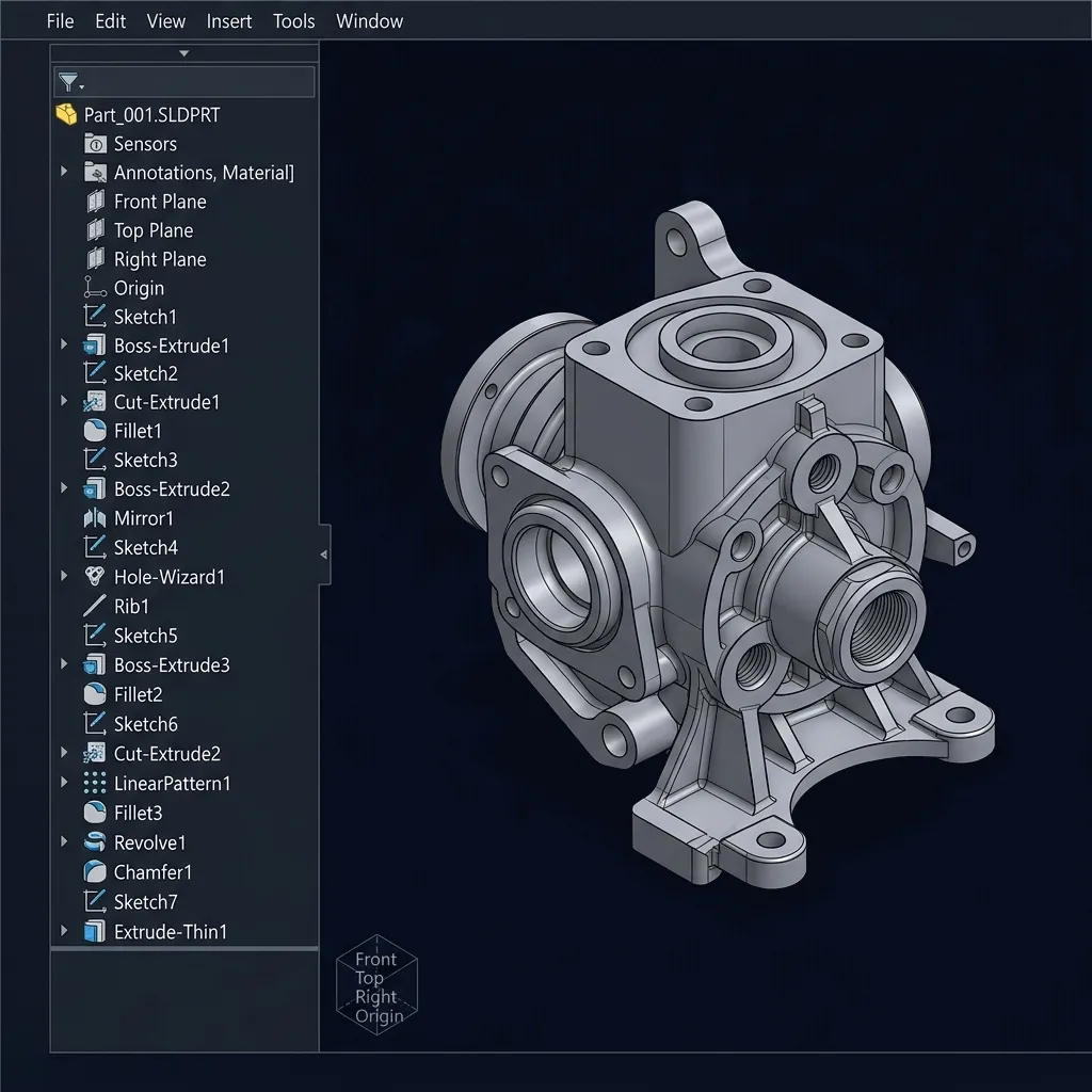
FALSE REJECTION DETECTOR

Best Fit Alignment
Inspection Service India

When the Part Isn't Wrong — But the Inspection Method Is.
Best fit 3D alignment analysis for manufactured parts India, helping casting, forging, fabrication and freeform surface manufacturers avoid unnecessary rework and scrap decisions.

4000+ Projects
1000+ Clients
9 Industries
6+ Years Exp

The False Rejection Story

A typical manufacturing incident timeline where rigid datum structures mask perfectly acceptable geometry.

Standard Datum Inspection

Inspection

Part is inspected using strict primary, secondary, and tertiary datums.

Part Rejected

Slight datum drift causes entire feature set to shift out of tolerance.

Production Delay

Machine stops. Scrap pile grows. Root cause analysis begins.

Best Fit Intervention
Best Fit Optimization

Best Fit Analysis

Scan data is globally optimized to the CAD model using iterative closest point (ICP).

Part Accepted

True geometry is revealed. Features are actually well within profile tolerance.

Production Saved

Rework avoided, delivery schedule met, scrap costs completely eliminated.

Best Fit vs Datum

Hover to reveal the mathematical differences.

Datum Alignment

Reference Driven Strict Constraint Heavy Deviation
VS

Best Fit Alignment

Geometry Driven Global Optimization True Geometry

How Best Fit Actually Works

Interactive Point Cloud Intelligence: Click a stage below to explore the geometry optimization mesh.

Scan Capture

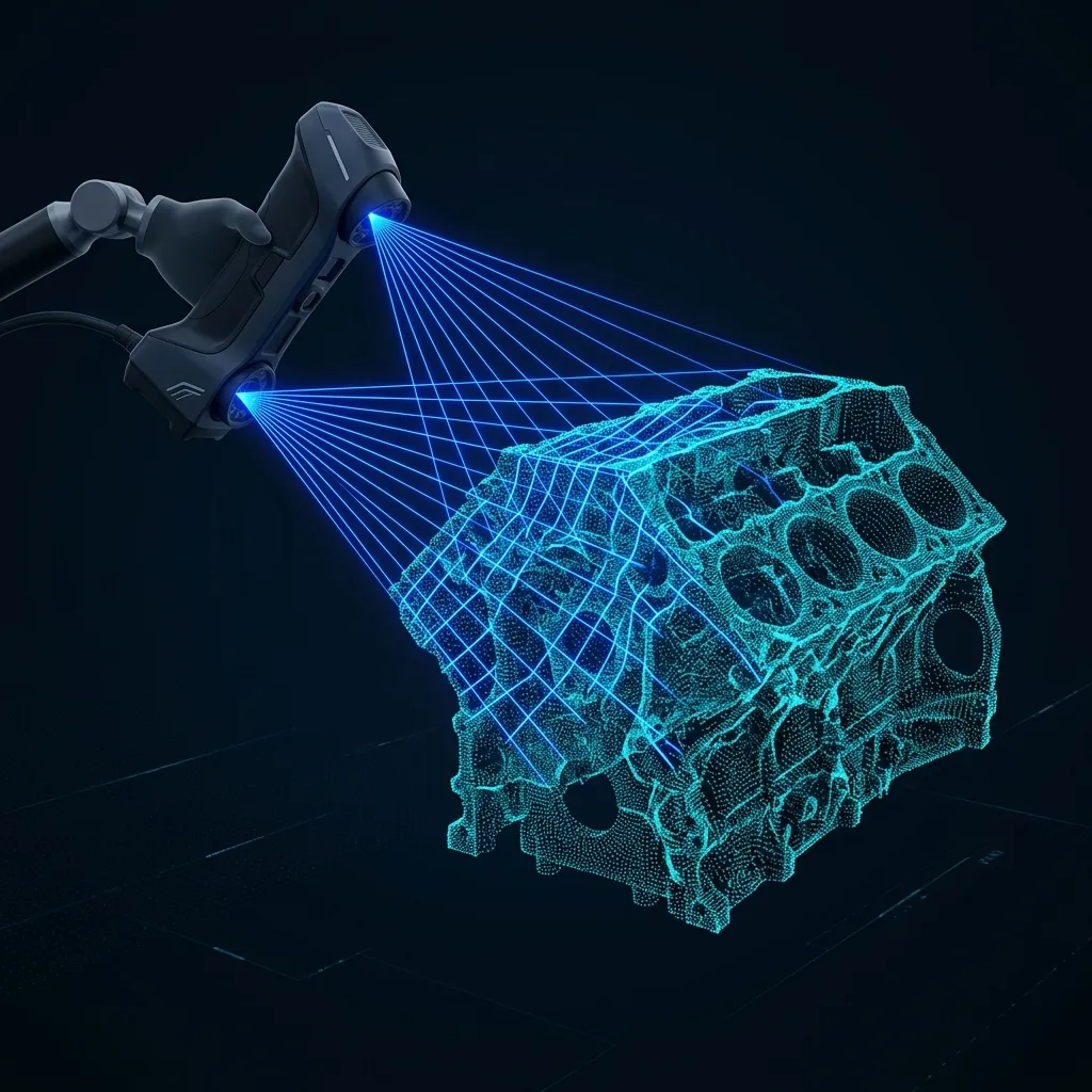
High-density point cloud geometry is captured using metrology-grade 3D scanning equipment, securing millions of data points representing the true physical condition.

Scan Capture

Point Cloud Import

The raw digital twin data is imported into specialized metrology software and overlaid roughly onto the nominal CAD model to establish the initial spatial bounding box.

Point Cloud Import

ICP Optimization

The Iterative Closest Point algorithm mathematically aligns the scan to the CAD, continuously calculating millions of point permutations to minimize global surface deviation.

ICP Optimization

Surface Matching

The physical geometry locks into its absolute optimal functional orientation. Instead of failing due to a single datum shift, it organically balances all feature variations simultaneously.

Surface Matching

Deviation Analysis

A highly accurate color-coded topography map is generated (Green = In Tolerance, Red = High, Blue = Low), instantly revealing the true manufacturing profile and validating acceptance.

Deviation Analysis

The Freeform Surface Challenge

Organic geometry lacks clear geometric datums (planes, cylinders). Best fit is the only reliable way to inspect these components.
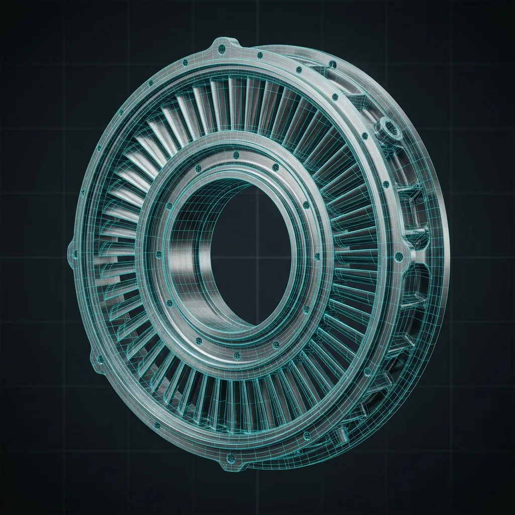
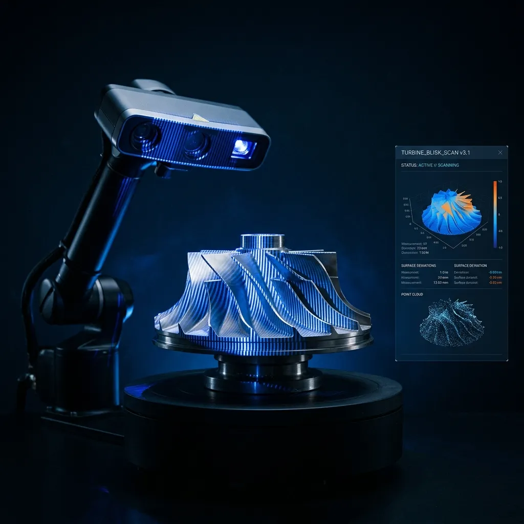
Turbine Blade

Turbine Blade

Complex airfoil profiles.
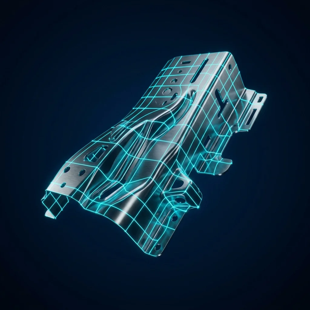
Best Fit Solution: Global Profile Alignment
Automotive Panel

Automotive Panel

Aesthetic flowing curves.

Best Fit Solution: Surface Match Alignment
Medical Implant

Medical Implant

Anatomical organic shapes.
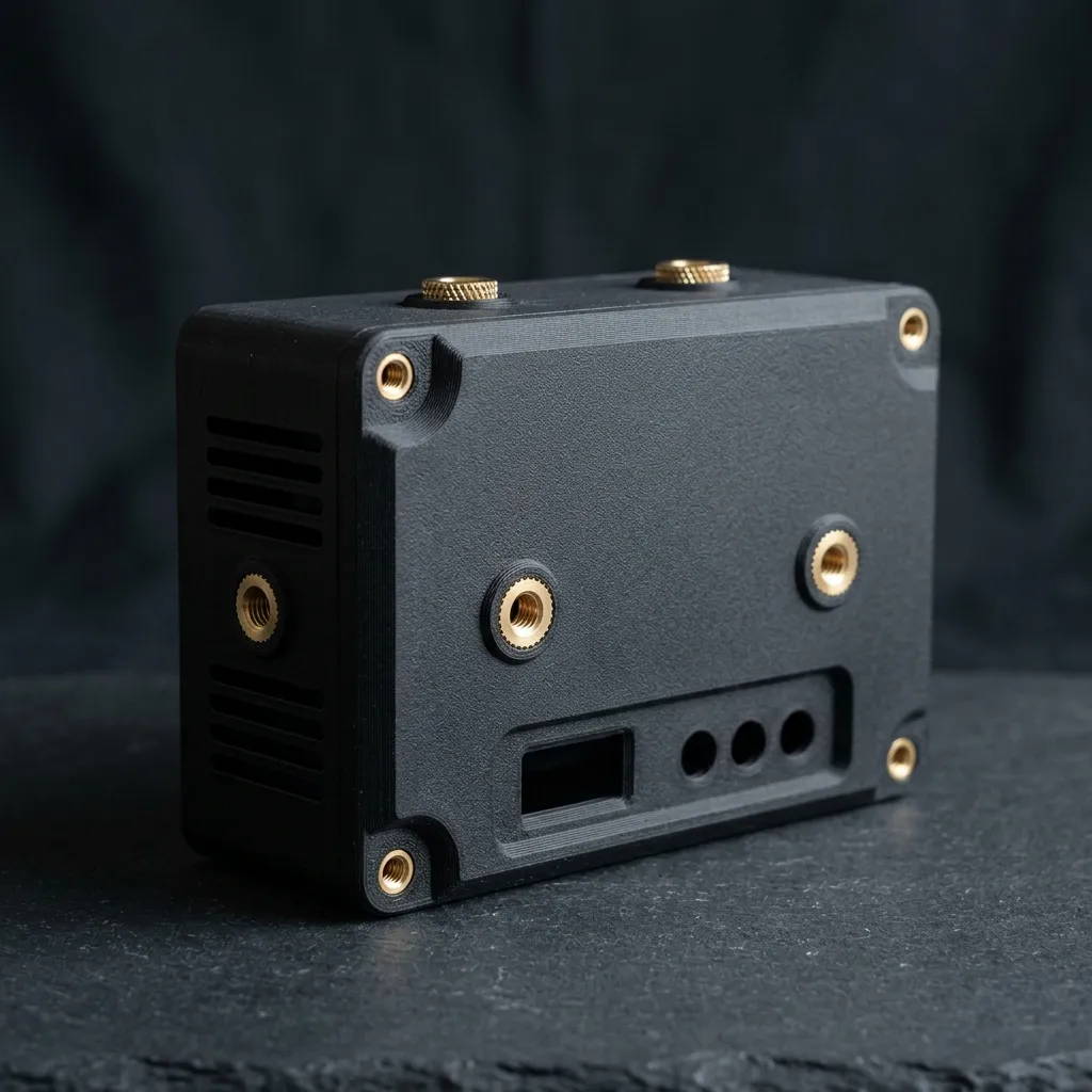
Best Fit Solution: Unconstrained Optimization
Agricultural Housing

Agricultural Housing

Large raw casting geometry.

Best Fit Solution: Shrinkage Balancing

Equipment Architecture

Interactive Decision Matrix: Select a technology to view precision specifications.
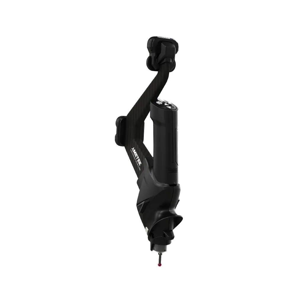
HandySCAN 3D
Ideal Part Size
0.1m - 4m
Tolerance
0.025 mm
Best Fit Application
Complex organic shapes, aerospace components, detailed castings.
MetraSCAN 3D
Ideal Part Size
0.5m - 15m+
Tolerance
0.050 mm
Best Fit Application
Large structural castings, automotive frames on the shop floor.
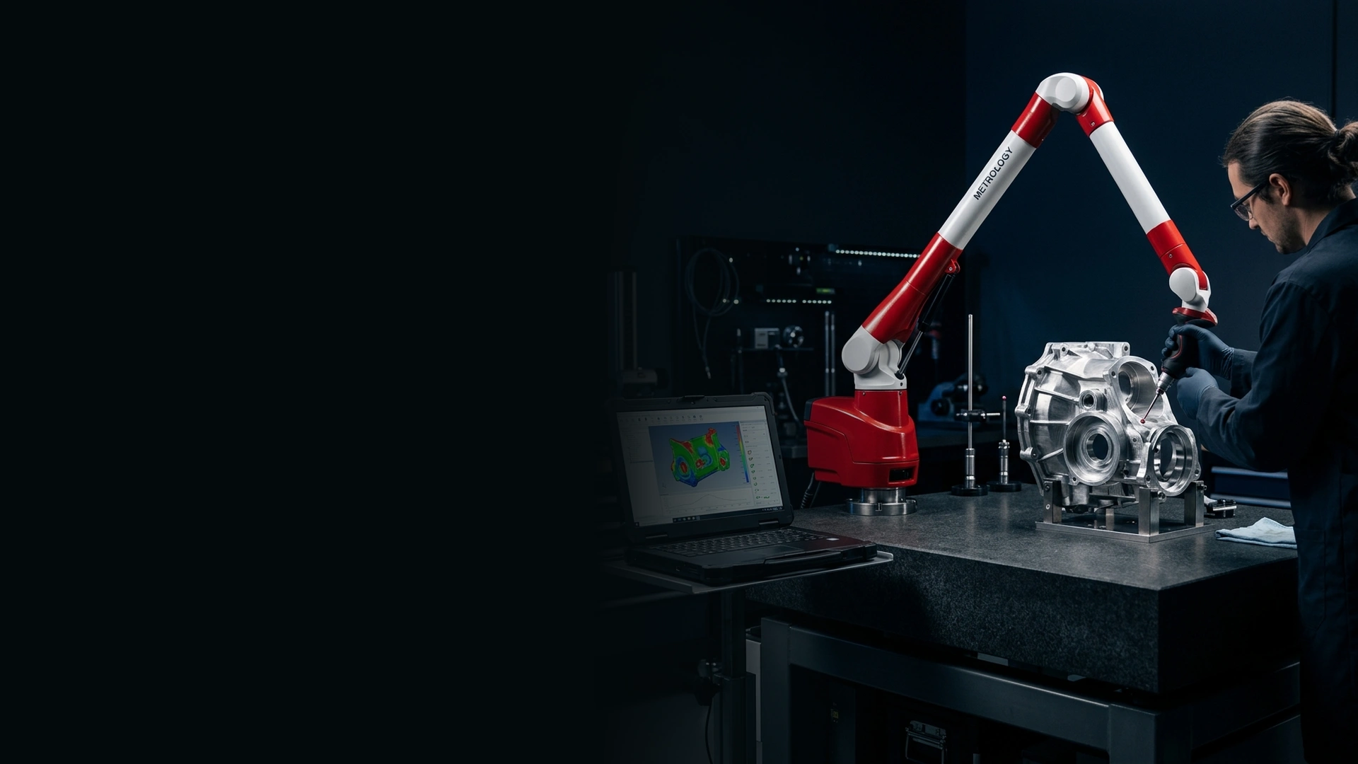
FARO Arm
Ideal Part Size
Up to 3m Volume
Tolerance
0.020 mm
Best Fit Application
Machined casting combinations requiring both probing and scanning.
ZEISS CMM
Ideal Part Size
Machine Bed Limit
Tolerance
0.005 mm
Best Fit Application
Extreme precision required, strictly controlled laboratory environment.
Laser Tracker
Ideal Part Size
10m - 160m
Tolerance
0.015 mm + 5 μm/m
Best Fit Application
Massive heavy machinery, shipbuilding, aerospace jigs & fixtures.

Foundry Digital Twin

Holographic Inspection Hub: Live raw variance analysis.
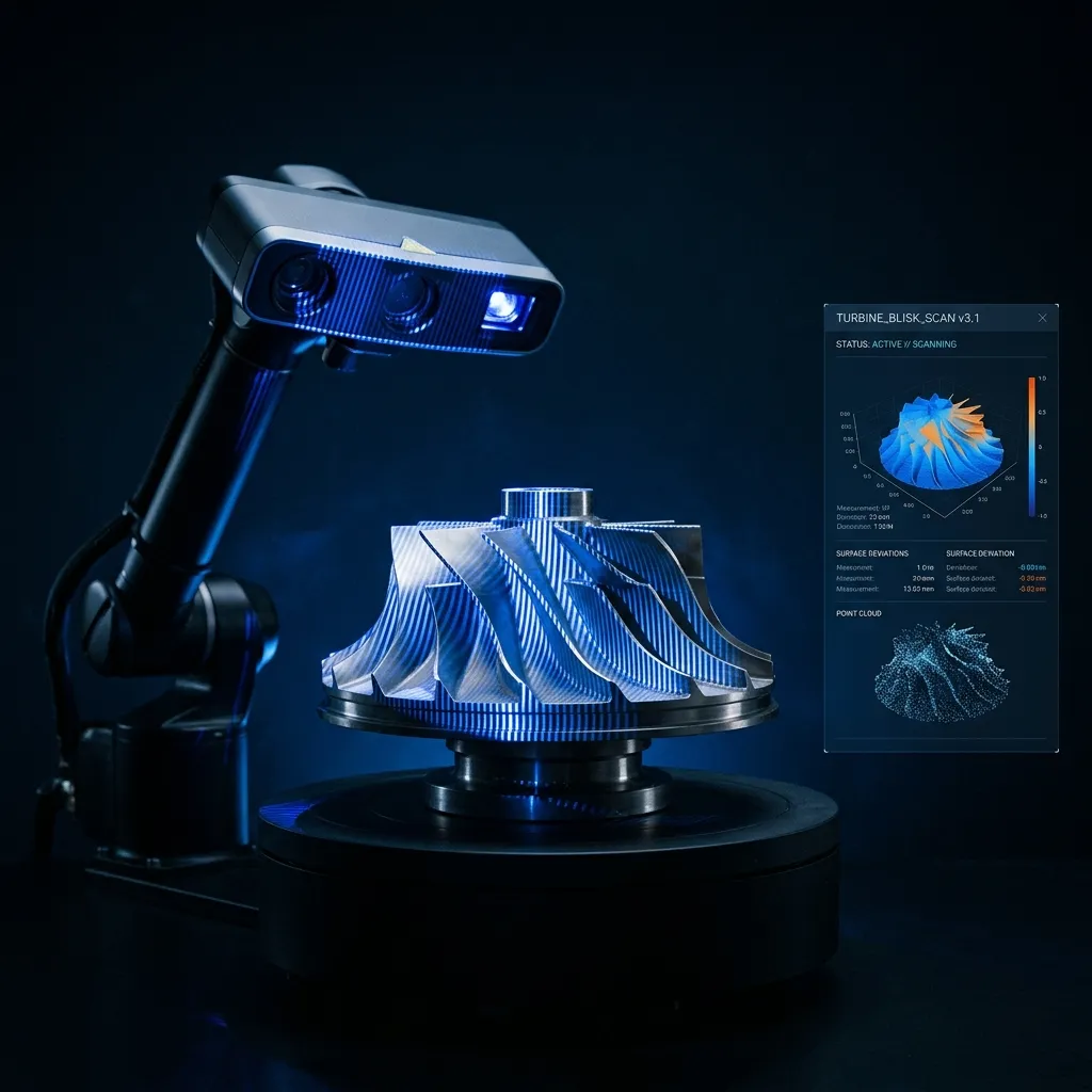
Shrinkage Variance

Visualizing post-cooling material contraction across the internal casting volume.

Draft Angles

Verifying extraction tapers against the nominal CAD for seamless mold release.

Material Flow

Identifying flow lines, turbulence traces, and potential cold shut zones.

Digital Twin Core

Shrinkage Variance

Visualizing post-cooling material contraction across the internal casting volume.

Machining Stock

Analyzing raw material allowance to guarantee clean CNC machining passes.

Surface Variation

Detecting organic surface deformations from non-uniform cooling gradients.

Geometry Drift

Measuring global distortion and twist caused by internal residual stresses.

Machining Stock Analysis

Cross Section Visualizer: Material removal simulation.
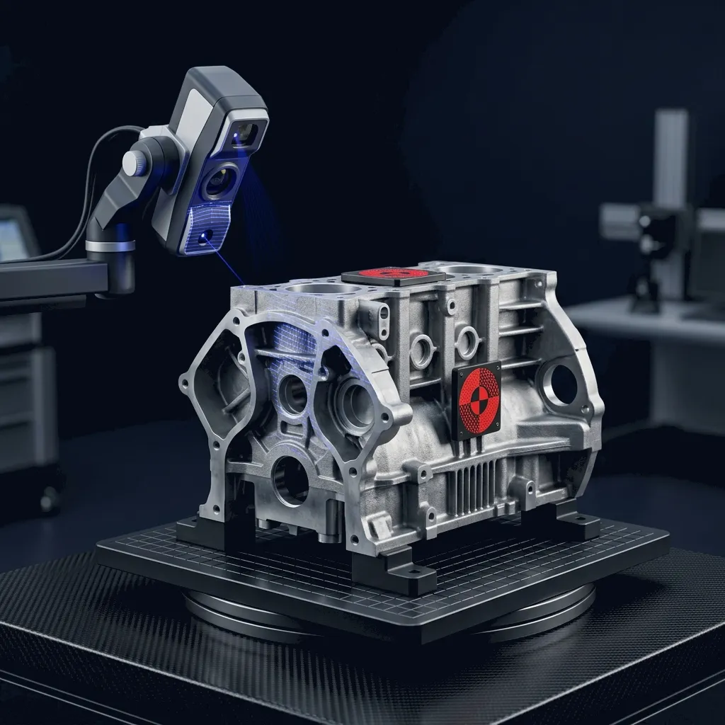
Raw Casting

Raw Casting

Machining Envelope

Machining Envelope

Finished Component

Finished Component

Proven Track Record

Real Project Case Study

Confidential Engineering Report Dashboard: Hover over the timeline below.

Automotive Casting
BATCH REJECTED
PRODUCTION RELEASED
Technical Service Overview Reviewed by APJ 3D Engineering Desk • Updated September 2026

What is Best Fit Alignment & 3D Metrology Services India?

Best Fit Alignment is a 3D metrology method that mathematically aligns a scanned point cloud to the nominal CAD model across the whole surface rather than fixed datums, letting freeform castings, forgings, and fabricated parts be inspected fairly instead of failing on a single misleading reference point.

When to Select This Service

Choose best fit alignment when a datum-based inspection is flagging a good part as out of tolerance, or when casting, forging, fabrication, and freeform-surface parts need an accurate rework-versus-scrap decision.

Best Fit Alignment & 3D Metrology Services India Technical Specifications

Technical Capabilities & Verification Standards

Verified engineering parameters, hardware precision, and compliance benchmarks applied across all deliverables.

Engineering Parameter APJ 3D Capability & Precision Range Compliance Standard / Verification
Measurement Equipment Bridge CMM (ZEISS / Renishaw), Portable Romer Arms, Laser Trackers, Vision Measuring Systems ISO 10360 Precision Compliance
Measurement Uncertainty Bridge CMM: E0 = 1.5 + L/350 µm; Portable Arm: ±0.025 mm; Laser Tracker: ±0.015 mm/m NABL / ISO 17025 Calibrated Standards
GD&T Verification Full ASME Y14.5 & ISO 1101 evaluation (Profile, True Position, Runout, Parallelism, Perpendicularity) Automated Inspection Programs
Inspection Frameworks AS9102 FAIR (Aerospace), AIAG PPAP Level 3 (Automotive), ISO 9001 Batch Quality Audits Standard Ballooned Drawing Reports
Inspection Environment Class 10,000 Temperature & Humidity Controlled Metrology Laboratory (20°C ± 0.5°C) Standard Reference Metrology Environment
Software & Reporting ZEISS CALYPSO, PolyWorks Inspector, PC-DMIS, Geomagic Control X Comprehensive Graphical & Tabular PDFs
Turnaround Time 24 to 48 Hours for standard First Article & batch inspection lots Pan-India On-Site CMM Arm Support
FAQ

Frequently Asked Questions

What is included in a First Article Inspection Report (FAIR)?

A FAIR includes a ballooned engineering drawing matching every dimension to an itemized inspection table, raw actual values, upper/lower tolerances, out-of-spec flags, and tool calibration certificates per AS9102 or customer templates.

Can you inspect parts according to PPAP Level 3 requirements?

Yes. We generate full dimensional results, Gage R&R studies, process capability studies (Cp/Cpk), material test reports, and Part Submission Warrants (PSW) for automotive Tier-1 supplier audits.

Do you provide on-site inspection for large tooling and weld fixtures?

Yes. Our metrology team deploys portable articulated arms and laser trackers directly to your manufacturing plant for on-site jig alignment, weldment inspection, and stamping die verification.

How do you establish datum reference frames for GD&T inspection?

We align physical components using primary, secondary, and tertiary datum features (planes, cylinders, holes) as specified on engineering drawings per ASME Y14.5M, eliminating alignment ambiguity.

What turnaround time can we expect for batch inspection?

Standard First Article inspections deliver in 24 to 48 hours. Ongoing production batch inspections can be scheduled with dedicated capacity and automated CMM routines.

The Part May Not Be The Problem.
The Inspection Method Might Be.

Get best fit deviation analysis service for casting and forging India, freeform surface inspection, and non constrained alignment inspection backed by APJ's metrology expertise.

ZEISS GOM Scan 1 OEM Ready Reports Pan India Service