DFA Evaluation Services
Build products that assemble faster and cost less. Our expert Design for Assembly Analysis radically reduces part counts, eliminates complex fastening, and error-proofs your production line.
Why Assembly Problems Happen
Products look perfect in CAD. But when they hit the assembly line, hidden inefficiencies emerge, driving up cycle times and labor costs.
DFA Evaluation Parameters
Our engineering framework systematically breaks down product architecture across six critical assembly vectors to guarantee manufacturing efficiency.
Evaluation
- Linear z-axis stacking
- Elimination of reorientations
- Sub-assembly consolidation
- Parallel vs sequential workflow
- Base part stability
- Multi-functional components
- Integral fasteners (snap-fits)
- Elimination of loose parts
- Theoretical minimum part criteria
- Consolidation of distinct materials
- Line-of-sight clearances
- Standardized tooling logic
- Pneumatic/Robotic access lanes
- Fastening envelope validation
- Blind assembly elimination
- Self-locating geometry
- Symmetrical vs extreme asymmetrical
- Tangle-resistant part design
- Automated feeding compatibility
- Handling ease indexing
- Impossible to assemble incorrectly
- Physical interference keys
- Clear visual alignment guides
- Feedback mechanisms (audible clicks)
- Mistake-proof fixturing
- Reverse engineered assembly indexing
- Best-in-class part count ratios
- Comparative fastening methodology
- Assembly time vs industry standard
- Supply chain commonality
Smart Assembly Analyzer
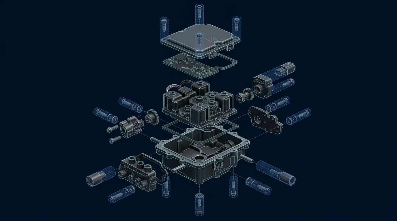
Evaluates standard vs custom fasteners, thread lengths, and driver access. Recommends snap-fits where structural integrity allows.
Simulates robotic end-effector and pneumatic tool envelopes to prevent clash during rapid assembly sequences.
Assesses chamfers, lead-ins, and locating pins for blind insertion capabilities without visual confirmation.
Verifies that cumulative tolerance stack-ups do not exceed functional assembly limits across mating components.
Analyzes cantilever and annular snap-fits for proper engagement strain, retention force, and moldability.
Before vs Optimized Assembly
See how our engineering analysis directly correlates to measurable reductions in part complexity and assembly time.
DFA Assessment Workflow
Secure ingestion of native product engineering files and existing assembly instructions.
Topology assessment to identify redundant parts and extreme asymmetric geometries.
Simulated mating and insertion sequences mapping clearance, tolerance, and fastening difficulty.
Comparison against industry-best equivalents to establish baseline component counts.
Comprehensive actionable redesign suggestions, cost reduction metrics, and optimized CAD snapshots.
Post-delivery consultation to assist manufacturing teams in executing the DFA redesigns.
Secure ingestion of native product engineering files and existing assembly instructions.
Topology assessment to identify redundant parts and extreme asymmetric geometries.
Simulated mating and insertion sequences mapping clearance, tolerance, and fastening difficulty.
Comparison against industry-best equivalents to establish baseline component counts.
Comprehensive actionable redesign suggestions, cost reduction metrics, and optimized CAD snapshots.
Post-delivery consultation to assist manufacturing teams in executing the DFA redesigns.
What is DFA Evaluation Services India?
Design for Assembly (DFA) Evaluation is a structured engineering analysis of a product's assembly sequence that identifies opportunities to reduce part count, eliminate complex fastening, and error-proof the production line.
When to Select This Service
Choose DFA evaluation when you need products that assemble faster and cost less, want to reduce part counts and fastener complexity, or need to benchmark assembly efficiency before production ramp-up.
Technical Capabilities & Verification Standards
Verified engineering parameters, hardware precision, and compliance benchmarks applied across all deliverables.
| Engineering Parameter | APJ 3D Capability & Precision Range | Compliance Standard / Verification |
|---|---|---|
| Part Count Reduction | Demonstrated reduction from 28 parts to 9 parts through consolidation and elimination of redundant components | Verified Part-Count Case Study |
| Assembly Time Reduction | Demonstrated reduction from 420 seconds to 110 seconds assembly time through DFA-driven redesign | Verified Assembly-Time Case Study |
| Fastener Analysis | Evaluation of standard versus custom fasteners, thread lengths, and driver access, with reduction from 12 screws to snap-fit-only assembly | Fastener Elimination Analysis |
| Snap-Fit Viability | Cantilever and annular snap-fit analysis for engagement strain, retention force, and moldability | Snap-Fit Engagement Verification |
| Error Proofing (Poka-Yoke) | Self-locating geometry and orientation features that eliminate reorientations and prevent incorrect assembly | Poka-Yoke Design Verification |
| Deliverables | Actionable redesign suggestions, cost reduction metrics, and optimized CAD snapshots | Actionable Design Recommendation Summaries |
Frequently Asked Questions
What information is required to start an FEA or CFD simulation?
What information is required to start an FEA or CFD simulation?
How do you validate the accuracy of simulation results?
How do you validate the accuracy of simulation results?
How can Moldflow simulation save tooling costs for plastic parts?
How can Moldflow simulation save tooling costs for plastic parts?
Can you optimize parts for lightweighting and material reduction?
Can you optimize parts for lightweighting and material reduction?
What is included in the final simulation report?
What is included in the final simulation report?
Build Products That Assemble Faster.
Leverage our definitive DFA Evaluation Services to reduce cycle times, minimize part counts, and eliminate manufacturing bottlenecks.