Engineering Services for
Plastics & Moulding
Manufacturers in India
Dimensional Control from Mould Qualification to Production Inspection. Ensure mould accuracy, reduce warpage, and maintain production quality with advanced 3D scanning.
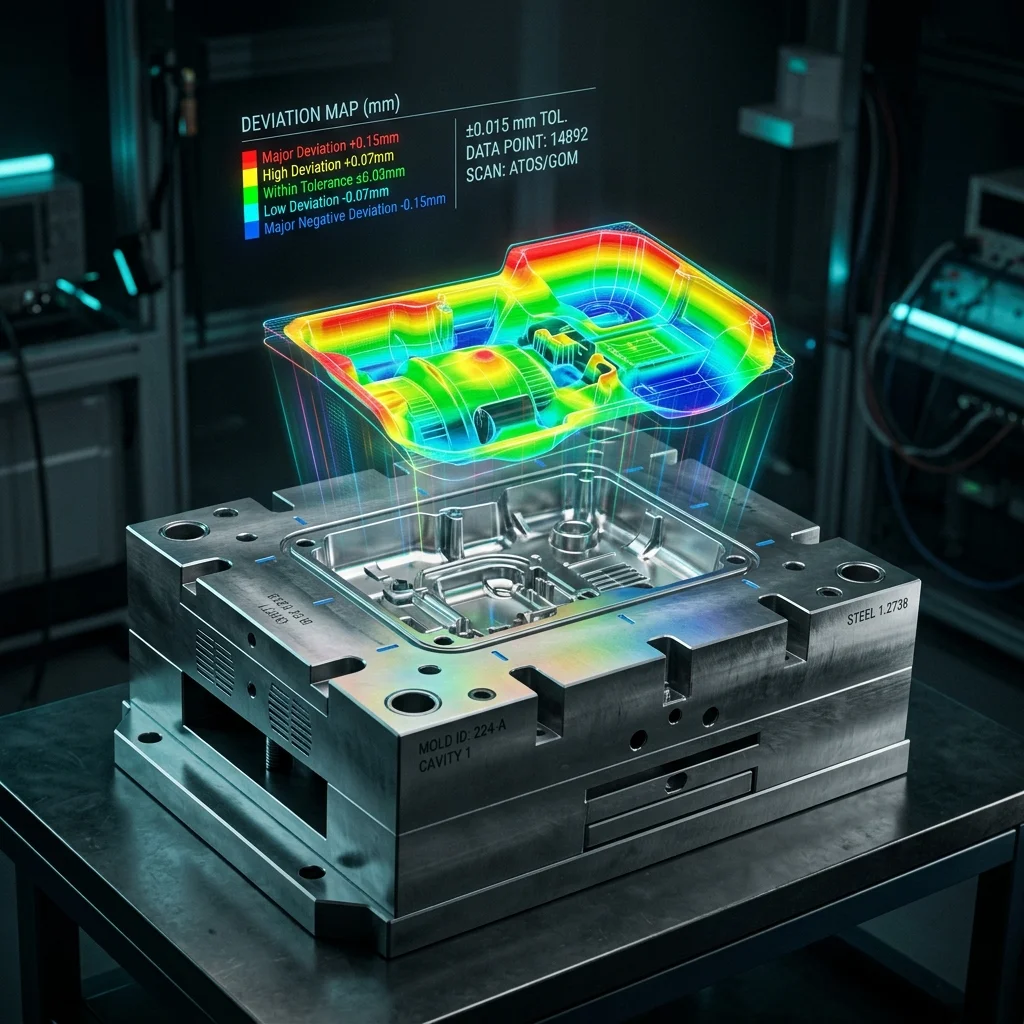
Engineering Support for Injection Moulding & Plastics Manufacturers
Dimensional engineering services purpose-built for injection moulding, tool validation, and warpage control.
APJ 3D provides 3D scanning and CMM inspection of injection moulds, tool wear and warpage analysis, First Article Inspection (FAI) reporting, reverse engineering of legacy tools, and updated 2D/3D documentation for plastics and moulding manufacturers across India. Plastic part quality is only as good as the mould that produces it. When a cavity wears, a cooling channel runs unevenly, or a gate is placed wrong, the defect doesn't show up as a design flaw — it shows up as a rejected batch on the production line. APJ 3D closes that gap with dimensional engineering services purpose-built for injection moulding: high-resolution 3D scanning to capture every surface of a mould cavity, and tool validation inspection to confirm a mould still holds its nominal geometry after thousands of shots.
We perform warpage and shrinkage analysis to trace whether a dimensional deviation originates in the tool, the process, or both. Where the original mould data is missing or the tool has been modified on the shop floor, our reverse engineering team rebuilds it into native, editable CAD so replacement cores, cavities, or replicated tooling can be manufactured with confidence. The result is fewer scrapped shots, faster First Article approvals, and a documented, auditable record of exactly what changed between the drawing and the physical mould.
Mould Qualification & FAI
New or reworked tools are scanned and measured against nominal CAD before production release, with GD&T reporting typically covering 80-200+ dimensional characteristics per cavity, so first-shot parts pass FAI and PPAP the first time. Reports are usually delivered within 24-48 hours of on-site scanning.
Wear & Warpage Diagnosis
Full-surface scanning isolates whether a rejected part is caused by cavity wear at the parting line (commonly 0.03-0.1mm after high shot counts), gate placement driving uneven fill pressure, or cooling-channel imbalance causing differential shrinkage — instead of guessing on the shop floor.
Legacy Tool Recovery
Undocumented or modified moulds are digitised into parametric, native CAD (SolidWorks, NX, CATIA) so spare cores, cavities, or duplicate tools can be manufactured accurately — turnaround scoped by tool complexity, from a single-cavity core to a multi-cavity family mould.
Tolerance Fails by Accumulation.
Mould wear, cooling stress, and shrinkage each contribute a small dimensional error, and those errors compound rather than cancel out. Dimensional variations multiply across the entire injection moulding process, and resolving part warpage requires tracking the complete compounding error chain back to its source.
Mould Wear & Degradation
Thermal cycling and abrasive resins cause steel cavities to drift out of nominal tolerance over hundreds of thousands of shots.
Cooling Stress & Shrinkage
Uneven cooling times and material flow dynamics create severe internal stresses resulting in geometric variations during ejection.
Part Warpage & Rejection
Unchecked deviations compound together, leading directly to assembly fitment failures, costly batch rejections, and material waste.

Full-Surface
Metrology Data
Traditional probing only checks a few discrete points. 3D scanning captures millions of data points across the entire physical part simultaneously.
This reveals exactly whether the dimensional deviation originates from the mould tooling itself, the injection and cooling process, or a combination of both.
Mould-Flow Analysis vs. Physical Mould Trials
Both methods answer the same question — will this mould produce a part within tolerance — but one answers it in software before steel is cut, and the other answers it on the shop floor after the tool already exists. Mould-flow and warpage simulation predicts fill, packing, and shrinkage behaviour up front, while physical T0/T1 trials confirm it with real parts.
- Gate location, cooling layout, and wall thickness issues are discovered only after the tool is cut and sampled
- Each correction loop means re-machining steel — typically days to weeks per iteration
- Warpage root cause (mould vs. process) has to be inferred from measured part data after the fact
- Multiple T1/T2 sample rounds are common before a new tool stabilizes within tolerance
- Steel rework, machine time, and scrapped shots are sunk costs on every failed trial
- Fill pattern, weld lines, air traps, and predicted shrinkage are visible before any steel is cut
- Gate position and cooling channel layout can be iterated in software in hours, not weeks
- Simulation directly separates process-driven warpage from tool-geometry-driven warpage
- Combined with 3D scanning of the T1 sample, simulation predictions are validated against the physical part in a single confirmation run
- Fewer physical iterations mean faster T1 approval and less scrapped material and machine time
The Complete Metrology Pipeline
A cohesive suite of services bridging the gap between physical production and digital perfection.
3D Scan & CMM
Sub-millimeter data capture using structural light scanning and metrology-grade probing.
Inspect & Warpage
Detect core micro-wear and perfectly map thermal deformation across the tool's lifecycle.
Reverse Eng.
Digitize and reconstruct legacy tools into fully feature-based parametric CAD models.
First Article (FAI)
Automated, comprehensive dimensional reporting designed to accelerate T0/T1 sample approvals.
CAD Docs
Update 2D prints and 3D models to flawlessly reflect the physical reality of the validated tool.
Mould Inspection & Warpage Analysis
Combine dimensional tool validation with thermal deformation analysis into one seamless, high-density scanning workflow.
Tool Degradation & Wear
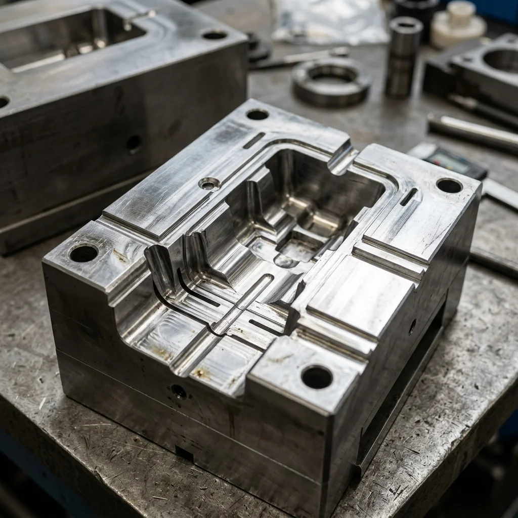
Scan legacy and high-volume tools during routine maintenance to detect micro-wear on parting lines, cores, and cavities long before they cause flash, sink marks, or rejected parts.
Cross-Section Deformation
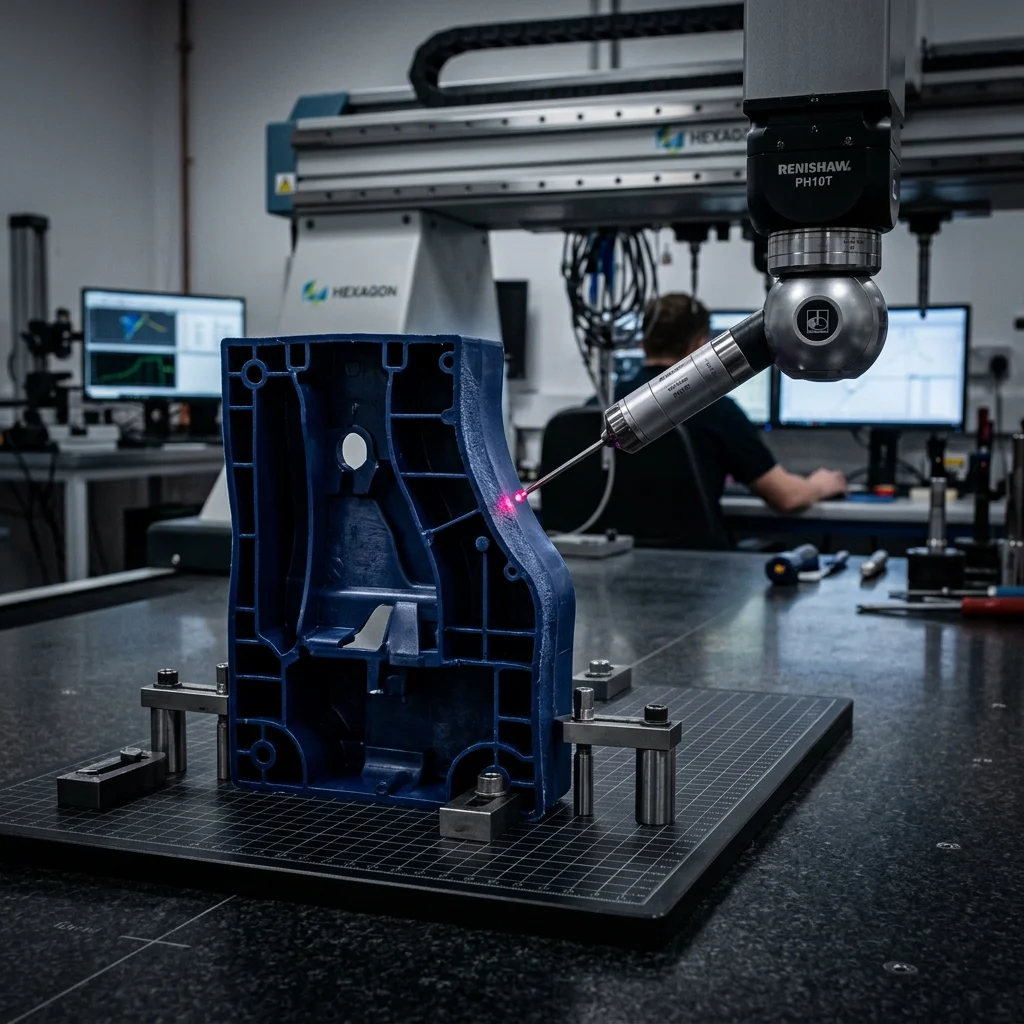
Track dimensional changes across the thermal lifecycle to isolate asymmetric shrinkage and warpage zones.
Actionable Engineering
- Gate Location & Flow Vector Tuning
- Cooling Channel Thermal Balancing
- Mathematical Scrap Reduction
First Article Inspection Workflow
Scan Component
High-resolution structured light scanning of the first injected batch.
Measure Features
Extract exact geometric data against nominal 2D drawings or 3D models.
Generate Report
Automated generation of detailed inspection reports mapping every tolerance.
Production Approval
Confident sign-off for mass production runs based on accurate metrology data.
On-Site Metrology & Digital Documentation
From shop-floor probing of heavy mould bases to the seamless delivery of parametric native CAD files.
Portable CMM Probing
Measure large mould bases and heavy tooling directly inside the moulding machine. Eliminate the massive downtime and logistics required for transportation.
Digital CAD Hub
Update out-of-date 2D prints and 3D models to perfectly match the physical, validated tool. Ensure future replication is flawless.
Why Manufacturers Choose APJ 3D
Full Mould Lifecycle Coverage
From initial mould qualification, through first article inspection, into serial production monitoring, and finally legacy tool recovery. We support every stage.
Full-Surface Scanning
Millions of points vs isolated touches.
Warpage Intelligence
Isolate thermal stress from physical wear.
Portable Metrology
We bring the CMM to your heavy moulds, eliminating logistics.
Legacy Recovery
Native CAD from old tools.
Fast Turnaround
Because downtime costs thousands.
Pan-India Support
Engineers deployed anywhere across the country.
What is Plastics and Moulding Engineering Services?
Engineering Services for the Plastics and Moulding Industry cover dimensional control across the mould lifecycle, from first-off mould qualification through production part inspection, using advanced 3D scanning to verify mould cavity accuracy, detect part warpage, and maintain consistent production quality.
When to Select This Service
Choose these engineering services when qualifying a new injection mould before production release, investigating warpage or shrinkage defects in moulded parts, or maintaining ongoing dimensional quality control across a plastics manufacturing line.
Technical Capabilities & Verification Standards
Verified engineering parameters, hardware precision, and compliance benchmarks applied across all deliverables.
| Engineering Parameter | APJ 3D Capability & Precision Range | Compliance Standard / Verification |
|---|---|---|
| Mould & Tool Inspection | 3D scanning and CMM inspection of injection moulds and mould bases, including tool wear and warpage analysis | First Article Inspection (FAI) Reporting |
| Cavity Wear Detection | Full-surface scanning isolates cavity wear at the parting line, commonly 0.03-0.1mm after high shot counts | Parting Line Wear Measurement |
| Root Cause Isolation | Distinguishes whether rejected parts stem from cavity wear, gate placement, or cooling-channel imbalance driving differential shrinkage | Cavity vs. Process Diagnosis |
| GD&T Reporting Coverage | Typically covers 80-200+ dimensional characteristics per cavity so first-shot parts pass FAI and PPAP the first time | PPAP-Ready GD&T Reports |
| Legacy Tool Reverse Engineering | Undocumented or modified moulds digitised into parametric, native CAD (SolidWorks, NX, CATIA) for spare cores and cavities | Native Parametric CAD Recovery |
| Turnaround Time | Single mould or cavity scan with dimensional report typically turned around within 24-48 hours of on-site data capture | 24-48 Hour Dimensional Reporting |
Frequently Asked Questions
Can you perform 3D scanning on-site at our manufacturing plant?
Can you perform 3D scanning on-site at our manufacturing plant?
How do 3D scanning and reverse engineering differ?
How do 3D scanning and reverse engineering differ?
What is a color deviation inspection map?
What is a color deviation inspection map?
Can dark, shiny, or transparent surfaces be scanned?
Can dark, shiny, or transparent surfaces be scanned?
What accuracy can we expect for automotive and aerospace components?
What accuracy can we expect for automotive and aerospace components?
Need Mould Inspection or Reverse Engineering Support?
From core and cavity wear detection to full legacy tooling recovery and portable CMM — APJ3D gives plastics manufacturers the dimensional intelligence to reduce scrap, fix tooling faster, and ensure perfect production.