Turbine Blade & Engine Component Analysis
Enter our precision metrology investigation. We non-destructively capture internal cooling channels, airfoil profiles, and thermal barrier coatings with sub-20 micron accuracy for advanced gas turbine benchmarking.
Tiny Geometric Deviations. Massive Performance Consequences.
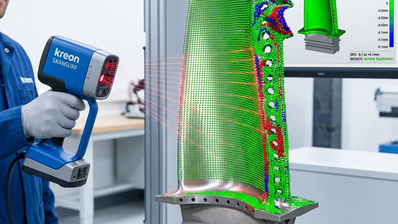
Leading Edge Radius Delta
A deviation of just +0.025mm on the leading edge profile dramatically alters high-Mach shockwaves, creating localized thermal hotspots and accelerating blade fatigue.
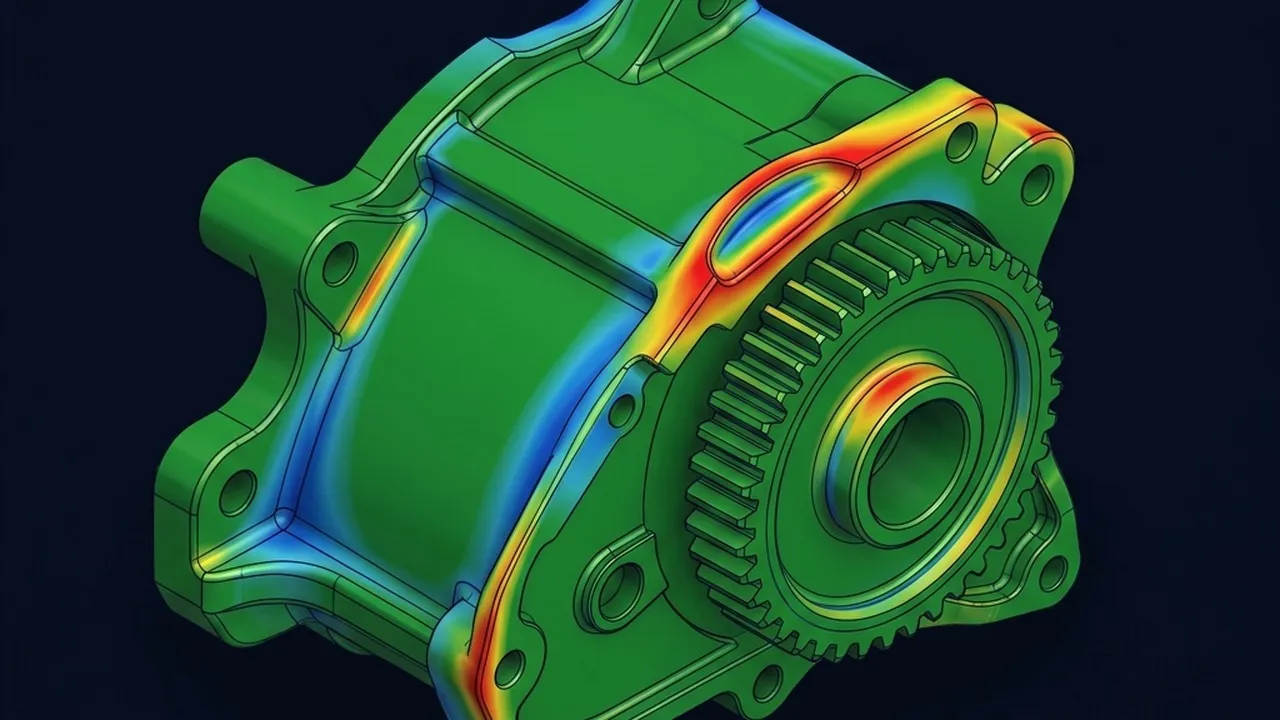
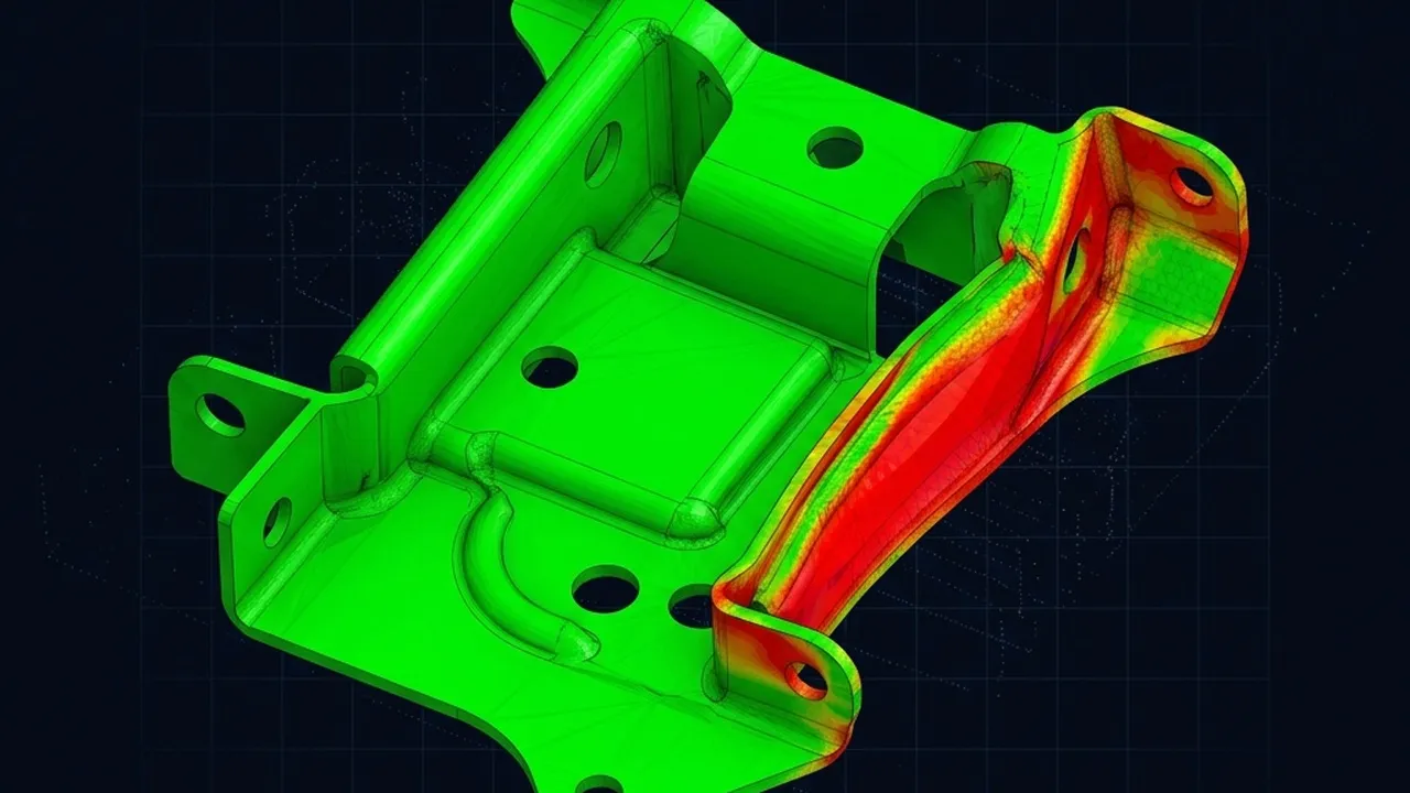
Precision Radial Measurement Protocol
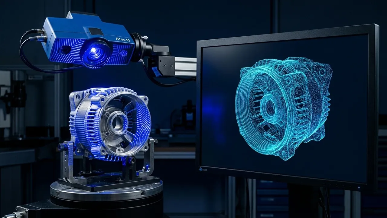
Precision Optical Structured Light Scanning
Deploying high-resolution blue light sensors to project triple-fringe patterns across airfoil surfaces, generating millions of verified dimensional coordinates in seconds.
Internal Blade Intelligence & Teardown
Internal Cooling Channels
High-pressure turbine blades endure gas temperatures far exceeding their melting point. We map intricate multipass internal serpentine channels, pin fins, and turbulence promoters to benchmark convective cooling efficiency.
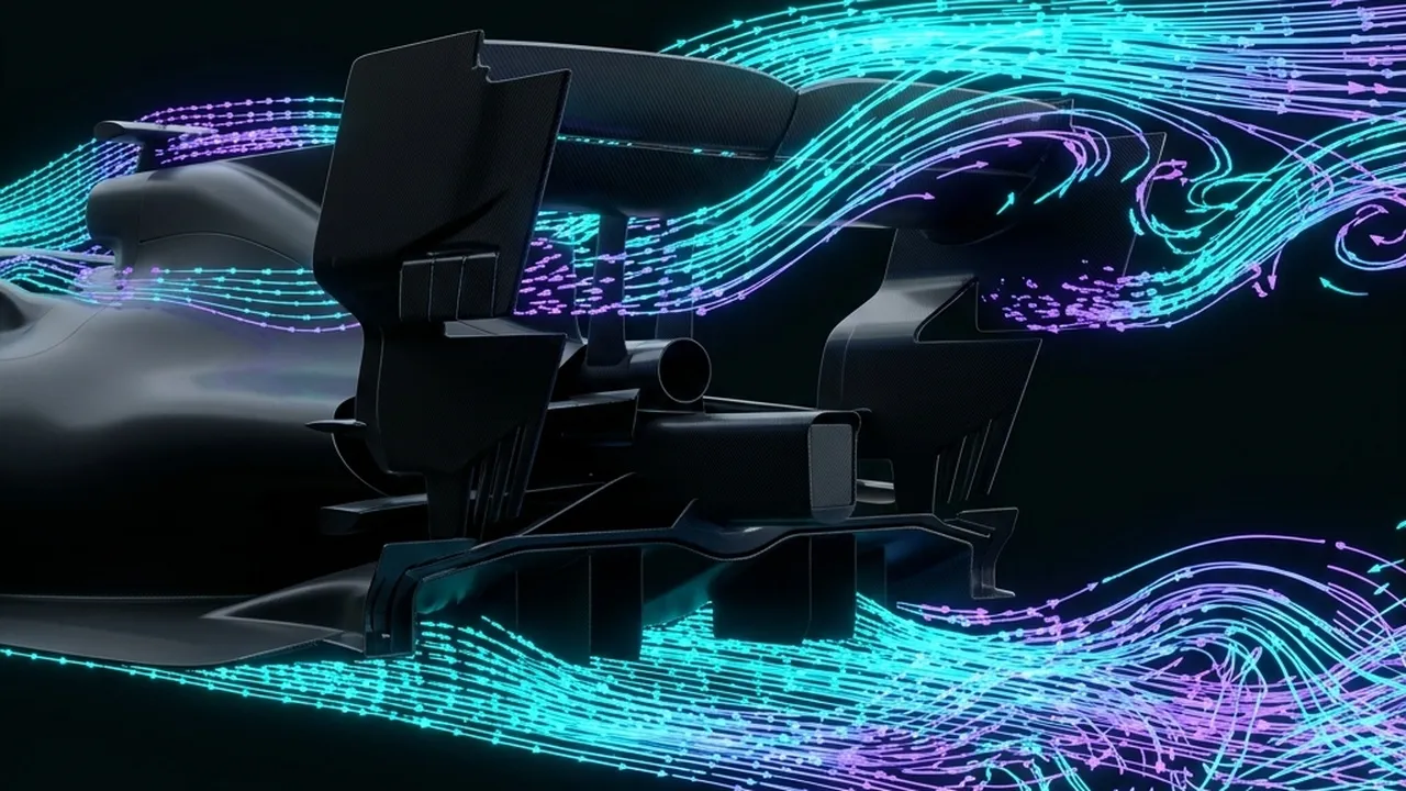
Interactive Engine Component Orbit
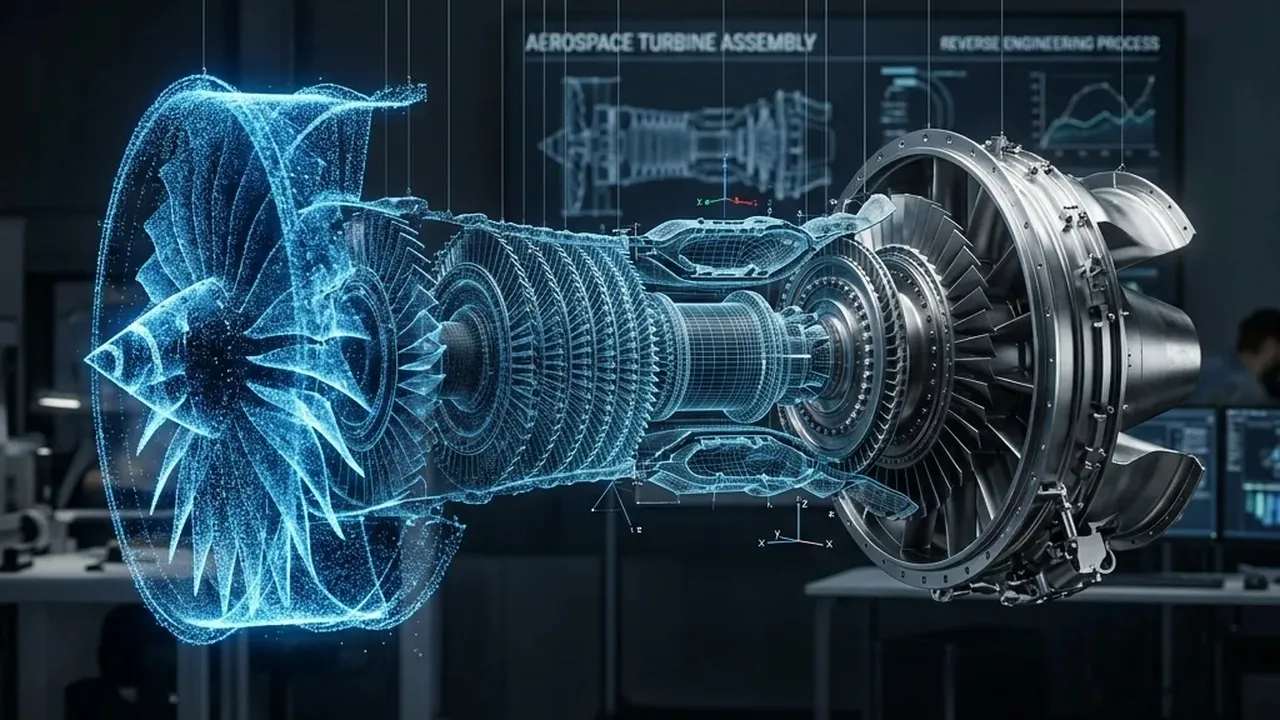
High-Pressure Turbine Blade
Extracting complete airfoil coordinates and camber line curvature. We deliver full 3D CAD datasets comparing leading competitor aero-thermodynamic blade designs.
Performance Interpretation Dashboard
Airfoil Accuracy & Camber Delta
Full chord-wise section analysis revealing a 99.8% geometric compliance to nominal blueprint curves, verifying superior aerodynamic boundary layer attachment.
Engineering Deliverables & Capabilities
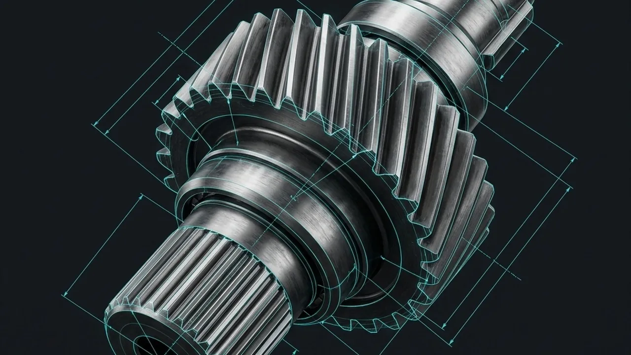
3D Color Deviation Analysis Dossier
Comprehensive inspection report comparing scanned physical turbine blades against nominal CAD models with cross-sectional slice overlays.
What is Turbine Blade & Engine Component Analysis?
Turbine blade and engine component analysis is a non-destructive precision metrology investigation that captures internal cooling channels, airfoil profiles, and thermal barrier coatings with sub-20 micron accuracy, enabling detailed geometric and dimensional benchmarking of complex gas turbine hardware.
When to Select This Service
Choose turbine blade and engine component analysis when you need to reverse engineer airfoil geometry, verify internal cooling channel dimensions, or benchmark competitor gas turbine hardware with sub-20 micron accuracy.
Technical Capabilities & Verification Standards
Verified engineering parameters, hardware precision, and compliance benchmarks applied across all deliverables.
| Engineering Parameter | APJ 3D Capability & Precision Range | Compliance Standard / Verification |
|---|---|---|
| Surface Scanning | High-resolution blue light structured light sensors projecting triple-fringe patterns across airfoil surfaces | Sub-20 Micron Accuracy |
| Internal Cooling Channel Capture | Non-destructive industrial CT scan data integrated with optical surface scans to map serpentine cooling passageways and turbulators | CT + Optical Data Fusion |
| Film Cooling Holes | Compound angular geometry, diffuser shaping, and diameter measurement of laser-drilled film cooling holes | Micro-Hole Geometry Verification |
| Wall Thickness & Core Shift | Verification of metal thickness between internal hollow cavities and exterior airfoil walls to detect casting core shift | Structural Integrity Check |
| Airfoil Profile Extraction | Complete airfoil coordinates and camber line curvature extraction, delivered as native CAD datasets for CFD ingestion | Parametric Airfoil Profile CAD |
| Superalloy Substrate Verification | Benchmarking of nickel-based single-crystal or directionally solidified superalloys for grain orientation and creep resistance | Metallurgical Core Analysis |
Frequently Asked Questions
Can you perform 3D scanning on-site at our manufacturing plant?
Can you perform 3D scanning on-site at our manufacturing plant?
How do 3D scanning and reverse engineering differ?
How do 3D scanning and reverse engineering differ?
What is a color deviation inspection map?
What is a color deviation inspection map?
Can dark, shiny, or transparent surfaces be scanned?
Can dark, shiny, or transparent surfaces be scanned?
What accuracy can we expect for automotive and aerospace components?
What accuracy can we expect for automotive and aerospace components?
Ready to Benchmark the Geometry That Drives Engine Performance?
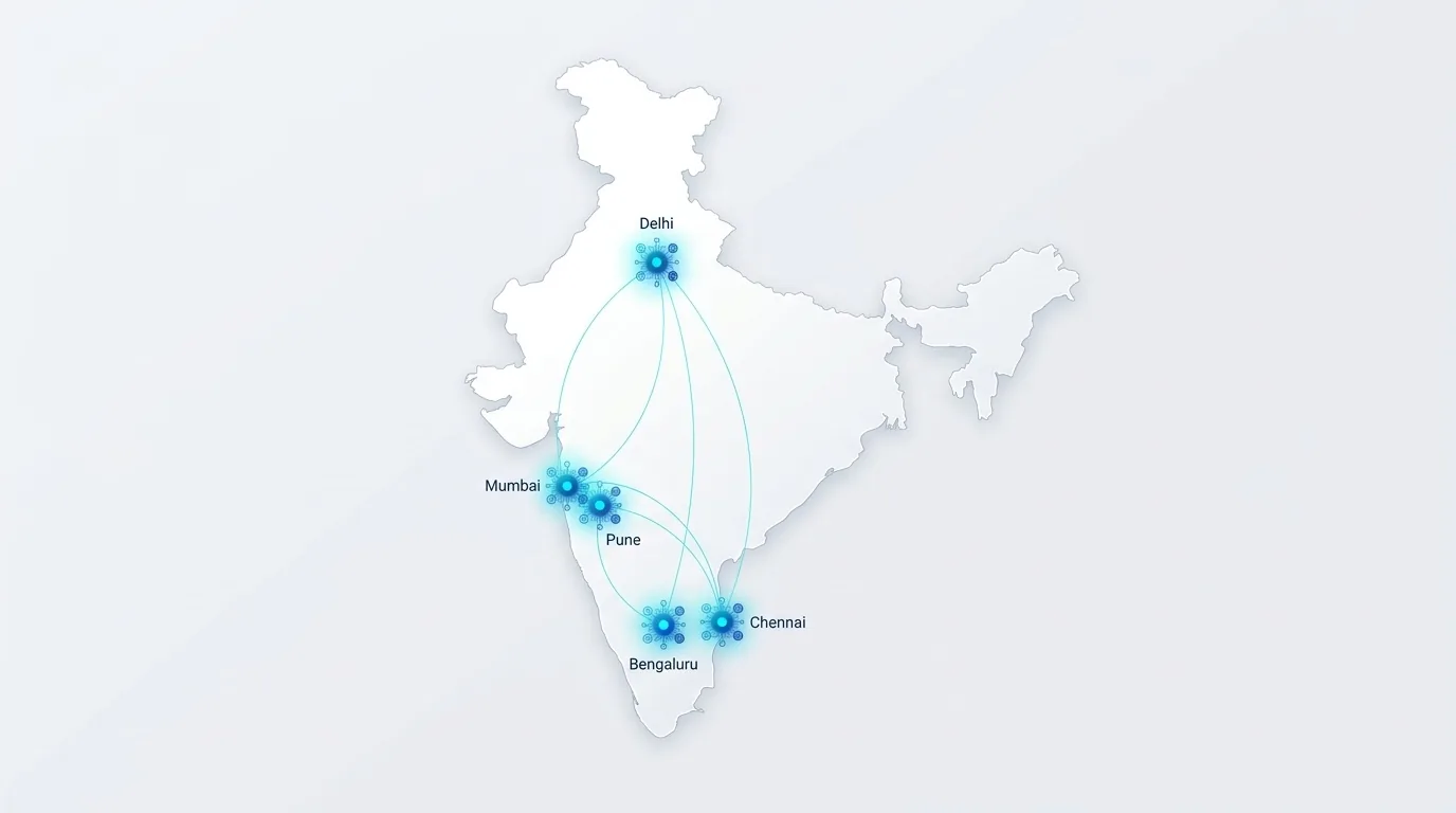
Empower your propulsion engineering team with sub-20 micron empirical intelligence. Schedule a turbine blade consultation across India.