3-2-1 Alignment
Inspection Service India
Datum-Traceable GD&T Inspection for Machined Components, Cast Parts & PPAP Validation.
The Most Trusted Starting Point in Dimensional Inspection
Incorrectly
Measurements
Applied
Frame
Begins
Without Datums, The Part Floats in Space
If a component is not properly constrained using a defined alignment strategy, its position and orientation relative to the scanner or CMM is entirely random. Every measurement taken will be inherently flawed.
Measurements Will Not Repeat
Without a locked coordinate system, repeating the scan will yield different results every time. You cannot establish true deviations if the baseline itself is constantly shifting.
Locking The 6 Degrees of Freedom
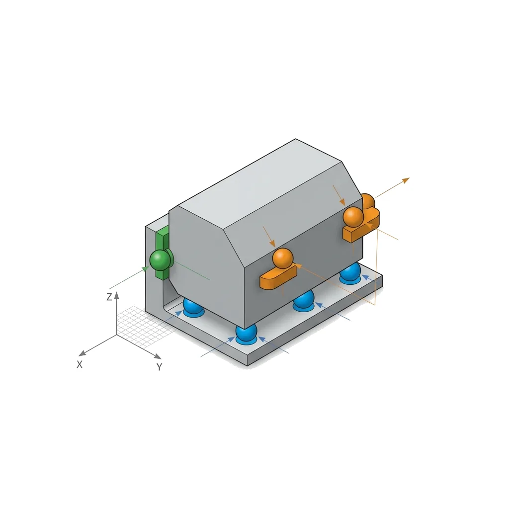
By applying 3 points to the primary datum plane, 2 points to the secondary axis, and 1 point to the tertiary stop, we mathematically arrest all movement in the X, Y, and Z axes.
A Traceable Origin is Born
The 3-2-1 intersection generates a flawless, repeatable coordinate system (0,0,0) that directly mirrors the engineering drawing's design intent.
Precision Inspection Unlocked
With the datums locked, every scanned feature is now precisely evaluated against its true position. The resulting inspection reports are perfectly aligned with manufacturing reality.
Six Contact Points. One Defined Coordinate System.
Tertiary Datum
Secondary Datum
Primary Datum
Why 3-2-1 Alignment Is Specified for Machined Components
Drawing Intent
Physical Inspection
Live 3-2-1 Alignment Simulator
Primary Datum
Locks 3 Degrees of Freedom
Secondary Datum
Locks 2 Degrees of Freedom
Tertiary Datum
Locks 1 Degree of Freedom
How 3-2-1 Connects to GD&T
Choosing the Right Alignment Strategy
From Drawing Datums to Verified Results
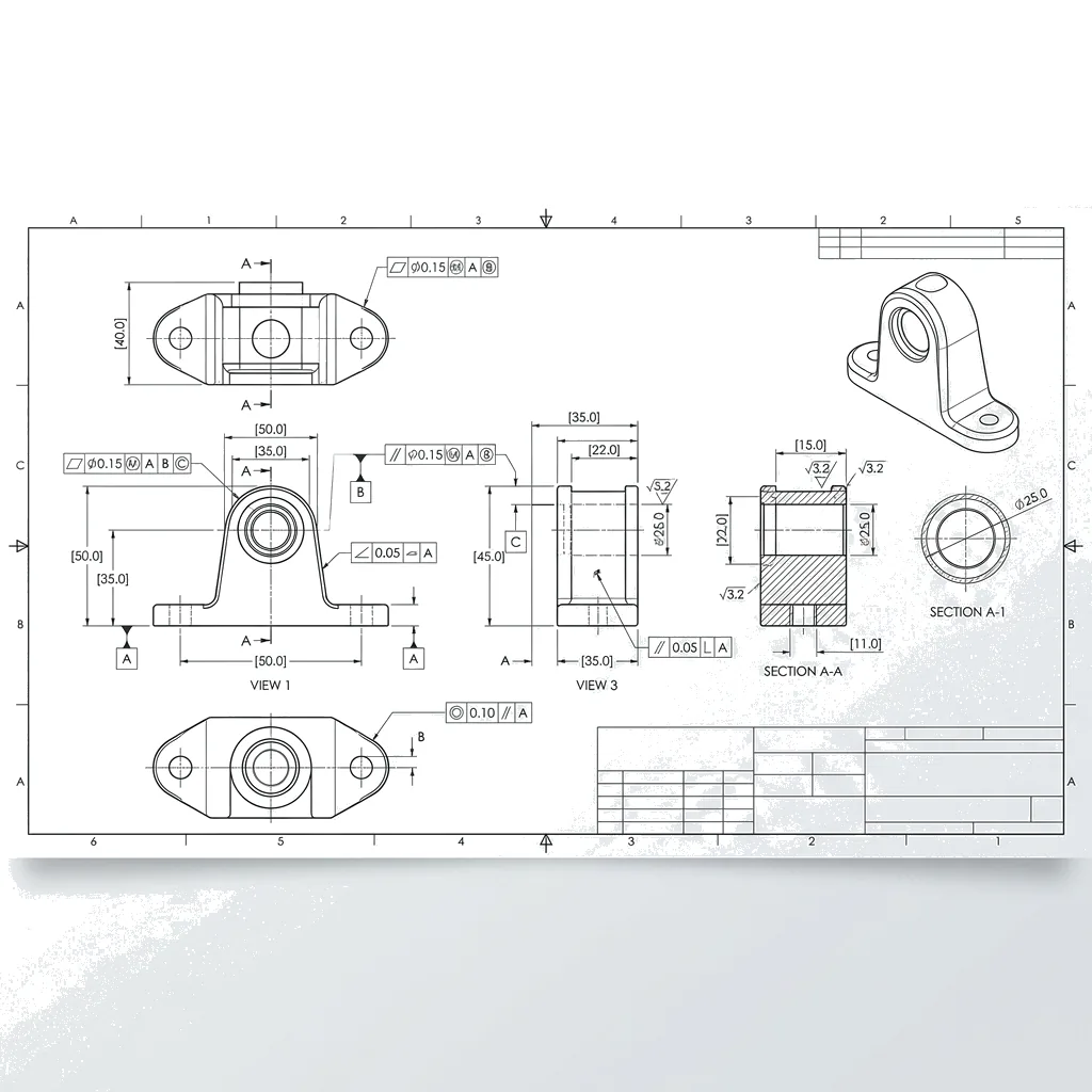
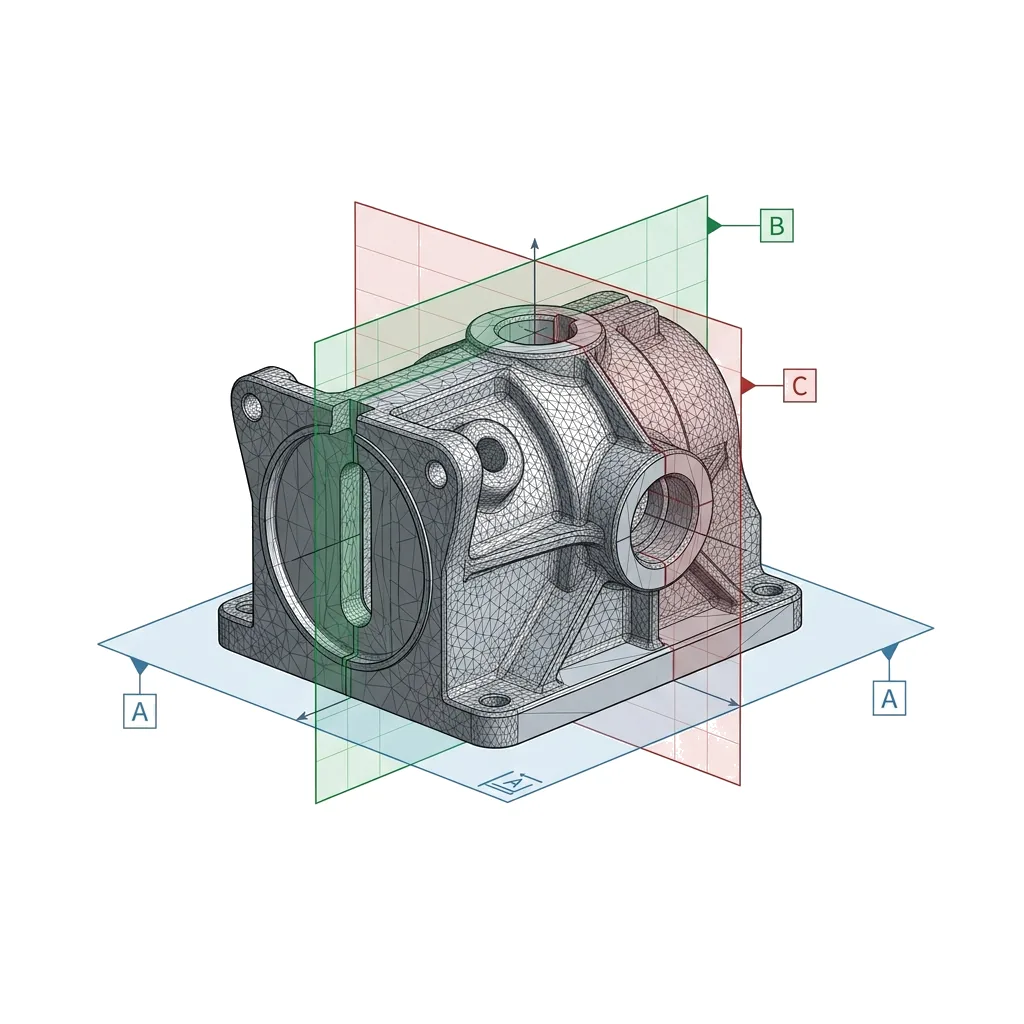
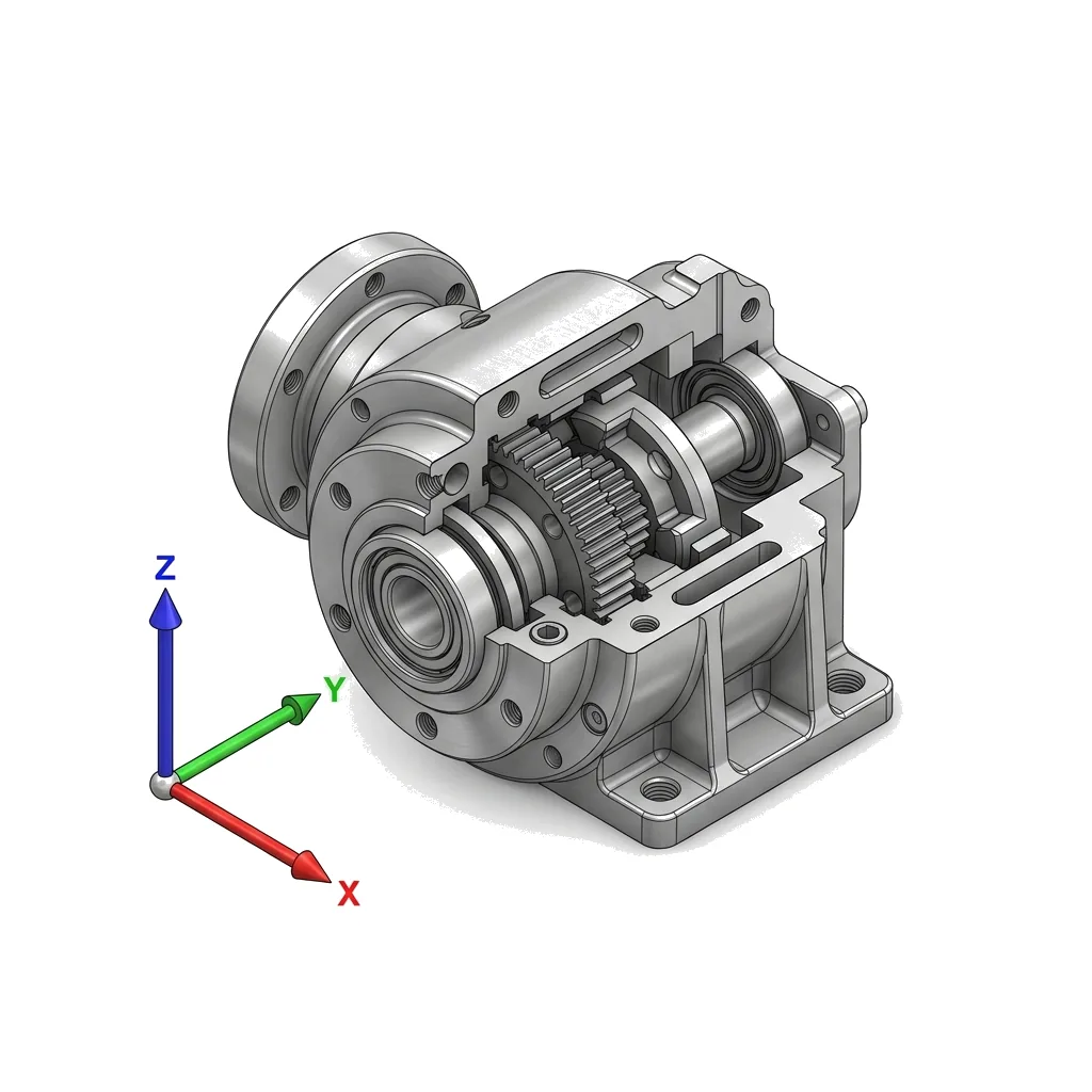
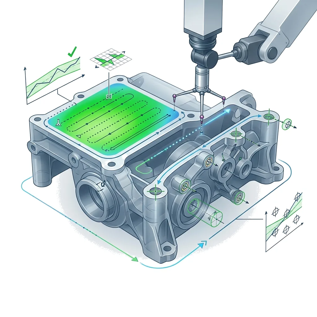
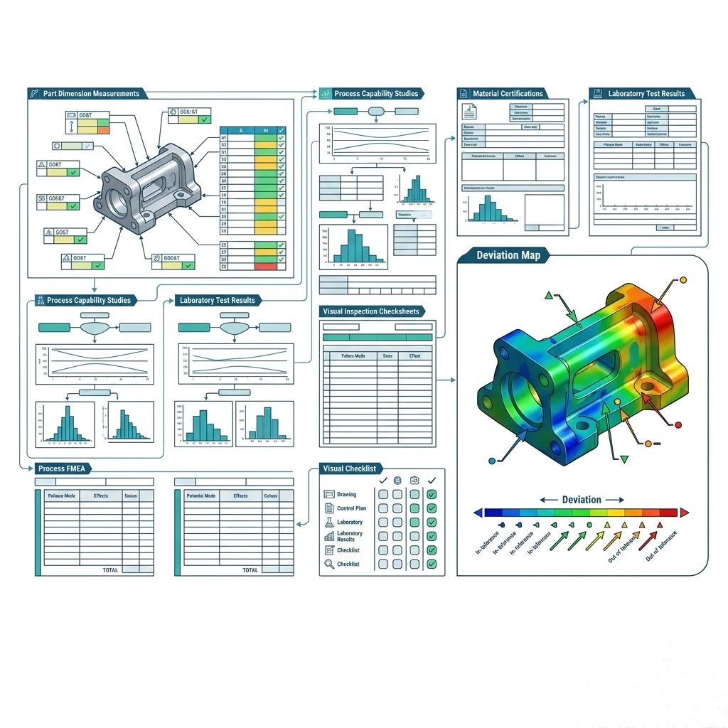
What is 3-2-1 Alignment Inspection Service India?
Dimensional Inspection is the formal verification of physical components against engineering drawings and CAD models using bridge CMMs, portable articulated arms, optical comparators, and laser trackers.
When to Select This Service
Choose dimensional inspection for First Article Inspection Reports (FAIR), PPAP Level 3 supplier submissions, batch quality audits, and shop-floor fixture alignment adhering to ASME Y14.5 and ISO 1101 standards.
Technical Capabilities & Verification Standards
Verified engineering parameters, hardware precision, and compliance benchmarks applied across all deliverables.
| Engineering Parameter | APJ 3D Capability & Precision Range | Compliance Standard / Verification |
|---|---|---|
| Measurement Equipment | Bridge CMM (ZEISS / Renishaw), Portable Romer Arms, Laser Trackers, Vision Measuring Systems | ISO 10360 Precision Compliance |
| Measurement Uncertainty | Bridge CMM: E0 = 1.5 + L/350 µm; Portable Arm: ±0.025 mm; Laser Tracker: ±0.015 mm/m | NABL / ISO 17025 Calibrated Standards |
| GD&T Verification | Full ASME Y14.5 & ISO 1101 evaluation (Profile, True Position, Runout, Parallelism, Perpendicularity) | Automated Inspection Programs |
| Inspection Frameworks | AS9102 FAIR (Aerospace), AIAG PPAP Level 3 (Automotive), ISO 9001 Batch Quality Audits | Standard Ballooned Drawing Reports |
| Inspection Environment | Class 10,000 Temperature & Humidity Controlled Metrology Laboratory (20°C ± 0.5°C) | Standard Reference Metrology Environment |
| Software & Reporting | ZEISS CALYPSO, PolyWorks Inspector, PC-DMIS, Geomagic Control X | Comprehensive Graphical & Tabular PDFs |
| Turnaround Time | 24 to 48 Hours for standard First Article & batch inspection lots | Pan-India On-Site CMM Arm Support |
Frequently Asked Questions
What is included in a First Article Inspection Report (FAIR)?
What is included in a First Article Inspection Report (FAIR)?
Can you inspect parts according to PPAP Level 3 requirements?
Can you inspect parts according to PPAP Level 3 requirements?
Do you provide on-site inspection for large tooling and weld fixtures?
Do you provide on-site inspection for large tooling and weld fixtures?
How do you establish datum reference frames for GD&T inspection?
How do you establish datum reference frames for GD&T inspection?
What turnaround time can we expect for batch inspection?
What turnaround time can we expect for batch inspection?
Start With the Right Datum.
End With the Right Decision.
Get Datum-Traceable 3-2-1 Alignment Inspection for Machined Components, Cast Parts & PPAP Validation Across India.