Engineering Services for
Foundries & Casting
Manufacturers in India
Dimensional Control from Pattern to Final Casting. We help foundries minimize scrap, optimize die tooling, and validate castings using advanced 3D scanning and inspection.
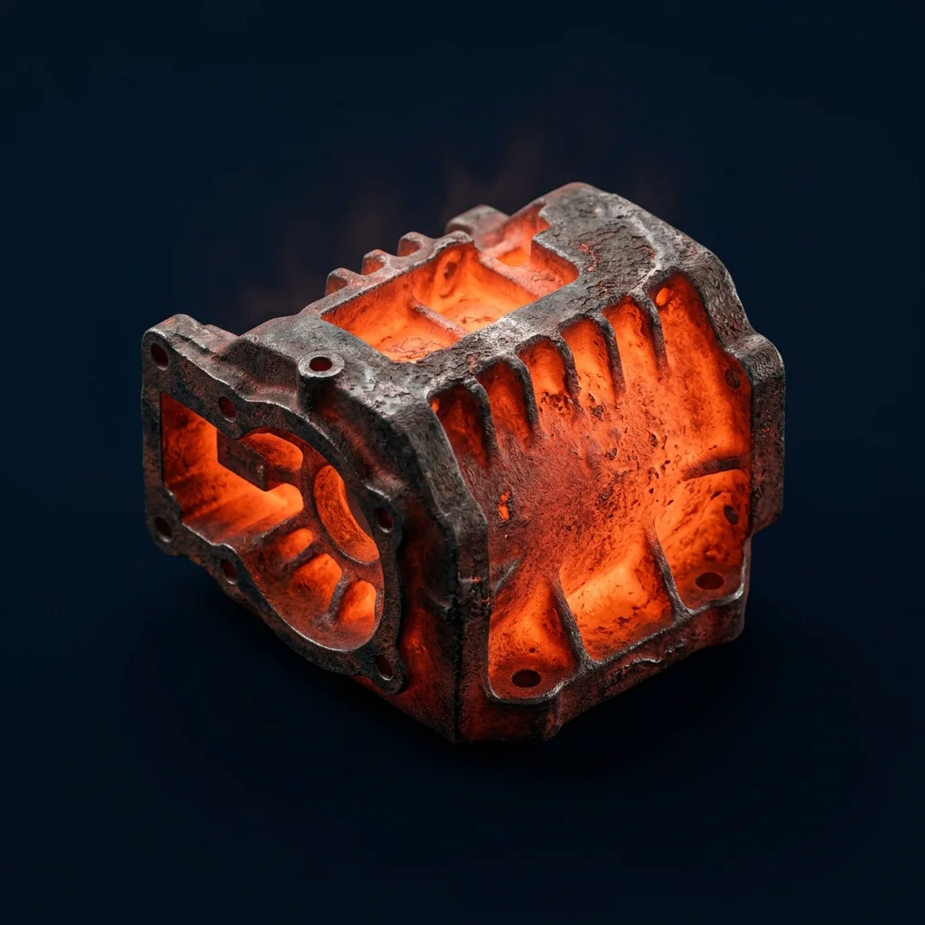
Why Casting Dimensions Drift From CAD
Precision dimensional metrology and reverse engineering giving foundries measured data to control shrinkage, core shift, and mould variation.
APJ 3D provides 3D scanning and casting inspection, pattern and die inspection, shrinkage and distortion analysis, portable CMM inspection for large castings, and reverse engineering of patterns and legacy tooling for foundries across India. Foundry and casting manufacturing carries dimensional risk that machined parts don't: metal shrinks unevenly as it solidifies, sand cores can shift inside a mould cavity, and every pour depends on how completely the molten metal actually filled the die.
APJ 3D's inspection and reverse-engineering services give foundries the measured data to control that risk — from the first trial casting through full production. By comparing high-density 3D scan data against nominal CAD models, our engineers pinpoint hot-spot shrinkage, wall thinning, and die mismatch early, protecting you against scrap batches and costly machining rework.
Shrinkage & Porosity Control
Non-uniform cooling means castings solidify at different rates across thick and thin sections — typical linear shrinkage allowance runs 1-2% for grey iron and 2-2.5% for aluminium alloys, and deviating from that pattern pulls geometry out of tolerance and drives internal porosity at hot spots. Full-surface 3D scanning maps deviation region by region, accurate to roughly ±25 µm, so pattern and die dimensions can be rescaled to compensate before the next pour.
Core Shift & Wall Thickness
Sand cores can move inside the mould during pouring under buoyancy and metallostatic pressure, thinning one wall while thickening the opposite side — a shift of even 0.5-1mm on a thin-wall casting can push a section below minimum design thickness. We compare scan data against nominal CAD, per ASME Y14.5 GD&T call-outs, to catch core shift and wall-thickness variation before parts reach machining, where the defect becomes far costlier to fix.
First-Off & Mould-Flow Validation
Before a new pattern, die, or mould-flow setup is approved for production, first-off casting inspection confirms the part matches design intent — surface, section, and datum by datum, typically reported within 48 hours of on-site or in-lab data capture. Catching mould-filling-driven dimensional variation — short shots, cold shuts, or misrun zones from poor gating — at this stage prevents an entire batch from being scrapped downstream. See how this compares to iterative trial-and-error casting below.
Mould-Flow Simulation vs. Trial-and-Error Casting Iterations
Both approaches aim to get a new pattern or die right, but they reach the answer very differently. Mould-flow and filling simulation predicts fill pattern, shrinkage, and porosity before metal is ever poured; trial-and-error relies on physically pouring, scanning, and reworking the tool until it passes — a slower and more expensive path to the same result.
- Each iteration requires a full pour, cool-down, and de-mould cycle — often 3-7 days per loop
- Shrinkage, porosity, and misrun defects are discovered only after metal has already been poured
- Root cause (gating, venting, or thermal gradient) has to be inferred from the defect pattern
- Typically needs 2-4 casting iterations before a new pattern or die stabilizes within tolerance
- Scrap metal, machine time, and pattern rework are sunk costs on every failed loop
- Fill pattern, solidification sequence, and shrinkage porosity are predicted before any metal is poured
- Gate location, riser sizing, and cooling channel layout can be optimized in software in hours, not days
- Root cause of predicted defects is visible directly in the simulation — no guesswork from a scrapped part
- Combined with first-off 3D scanning, simulation-predicted geometry is validated against the real casting in a single confirmation pour
- Cuts tooling iteration cycles and gets a new pattern or die to production faster with less scrapped metal
Dimensional Variation Is Inherent.
Controlling It Requires Data.
Shrinkage, core shift, die wear, and thermal distortion are the four dimensional problems every foundry deals with, and each one needs a different measurement approach to catch before it becomes scrap.
Shrinkage & Porosity
Uneven cooling causes internal dimensional shrinking, pulling geometry out of tolerance.
Core Shift
Unpredictable movement of internal sand cores results in uneven wall thicknesses.
Die & Pattern Wear
Repeated casting causes expensive molds to degrade, shifting parts out of tolerance.
Thermal Distortion
Extreme heat gradients during cooling cause the casting to warp and twist.
Full Lifecycle Engineering Support
Engineering Support
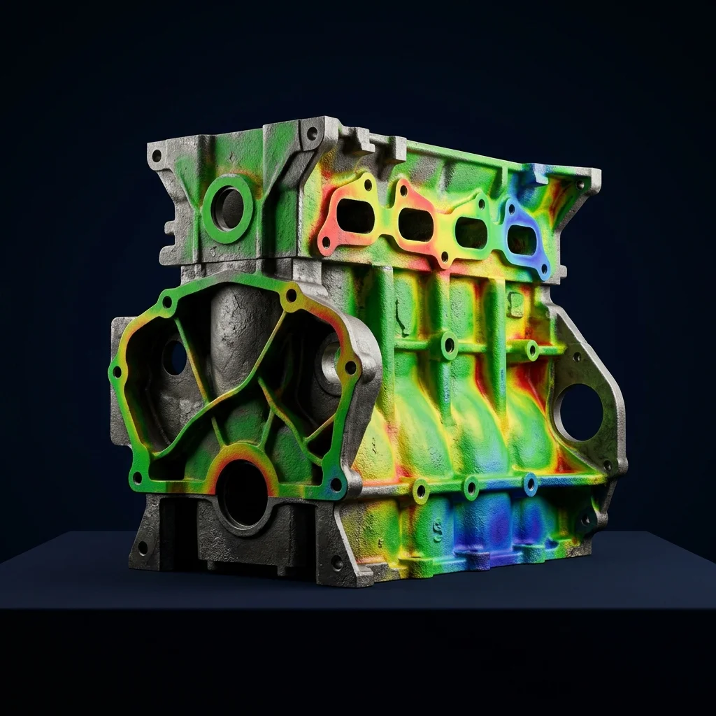
Full Surface Inspection
Without Blind Spots
Our structured light and laser scanning systems capture millions of points in seconds — providing a complete digital twin of your casting for full evaluation.
Detect Wear Before It Causes Scrap
Tooling degrades over time. Our inspection compares physical patterns and dies back to the original CAD to identify wear, flash, and surface degradation.
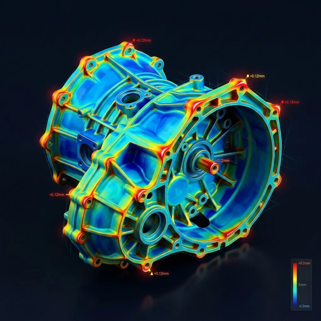
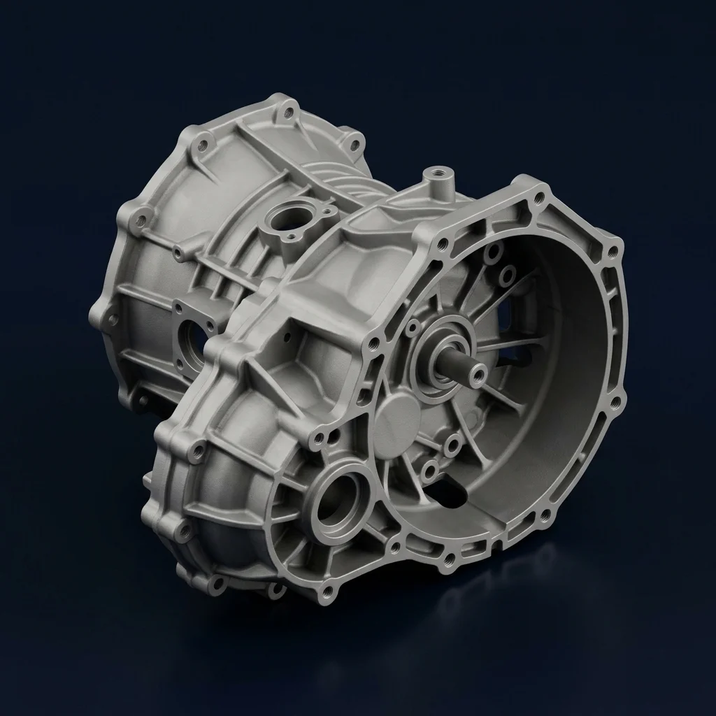
Scan to CAD Workflow
Shrinkage &
Distortion Analysis
Turn scan data into actionable corrections — track defects, compensate shrinkage, and optimize tooling.
3D Inspection ServicesShrinkage Detection
Map non-linear shrinkage across complex geometries to fine-tune scaling.
Distortion Tracking
Identify twist, warp, and bending from uneven cooling to fix parameters.
Core Movement
Detect and correct core shifts via internal cavity and wall thickness analysis.
Tooling Correction
Finalize mold designs with precise compensation data derived from scan results.
Manufacturing-Ready CAD Documentation
All deliverables are inspection-report backed and ready for direct upload to your PLM system.
2D Drafting Services ?We Come To Your Foundry
Large structural castings and heavy machine beds can't be moved to a lab. Our portable CMM engineers deploy directly to your facility — capturing metrology-grade data right on the shop floor.
Trusted Engineering
Partner for Foundries
From first article inspection to legacy tooling recovery — we cover the full casting lifecycle with metrology-grade precision and on-site flexibility.
What is Foundry & Casting Industry Engineering Solutions?
Foundry and Casting Industry Engineering Solutions apply dimensional control from pattern to final casting, combining 3D scanning, reverse engineering, and inspection to help foundries minimize scrap, optimize die and pattern tooling, and validate castings against design intent.
When to Select This Service
Choose these engineering solutions when a foundry needs to reduce scrap rates, validate pattern and die tooling accuracy, benchmark casting wall thickness and shrinkage, or inspect finished castings against master CAD models.
Technical Capabilities & Verification Standards
Verified engineering parameters, hardware precision, and compliance benchmarks applied across all deliverables.
| Engineering Parameter | APJ 3D Capability & Precision Range | Compliance Standard / Verification |
|---|---|---|
| Shrinkage & Porosity Control | Full-surface 3D scanning maps deviation region by region, accurate to roughly ±25 µm, against typical linear shrinkage allowances of 1-2% for grey iron and 2-2.5% for aluminium alloys | Pattern & Die Rescaling |
| Core Shift & Wall Thickness | Scan data compared against nominal CAD, per ASME Y14.5 GD&T call-outs, to catch core shift and wall-thickness variation before parts reach machining | ASME Y14.5 GD&T Verification |
| First-Off & Mould-Flow Validation | Mould-flow and filling simulation predicts fill pattern, shrinkage, and porosity before metal is poured, cutting tooling iteration cycles versus trial-and-error casting loops | Mould-Flow & Filling Analysis |
| Pattern & Die Wear Inspection | Physical patterns and dies compared back to the original CAD to identify wear, flash, and surface degradation before it causes scrap | CAD-to-Physical Comparison |
| Casting Process Coverage | Sand castings, investment castings, and die castings all supported across the same 3D scanning and inspection workflow | Multi-Process Coverage |
| Turnaround Time | Most scan-to-report engagements are completed within 48 hours of on-site or in-lab data capture | Scan-to-Report SLA |
Frequently Asked Questions
Can you perform 3D scanning on-site at our manufacturing plant?
Can you perform 3D scanning on-site at our manufacturing plant?
How do 3D scanning and reverse engineering differ?
How do 3D scanning and reverse engineering differ?
What is a color deviation inspection map?
What is a color deviation inspection map?
Can dark, shiny, or transparent surfaces be scanned?
Can dark, shiny, or transparent surfaces be scanned?
What accuracy can we expect for automotive and aerospace components?
What accuracy can we expect for automotive and aerospace components?
Stop Casting Rejects Before They Start
From pattern inspection and shrinkage analysis to full die documentation and portable CMM — APJ3D gives foundries the dimensional intelligence to reduce scrap, fix tooling faster, and get castings right.