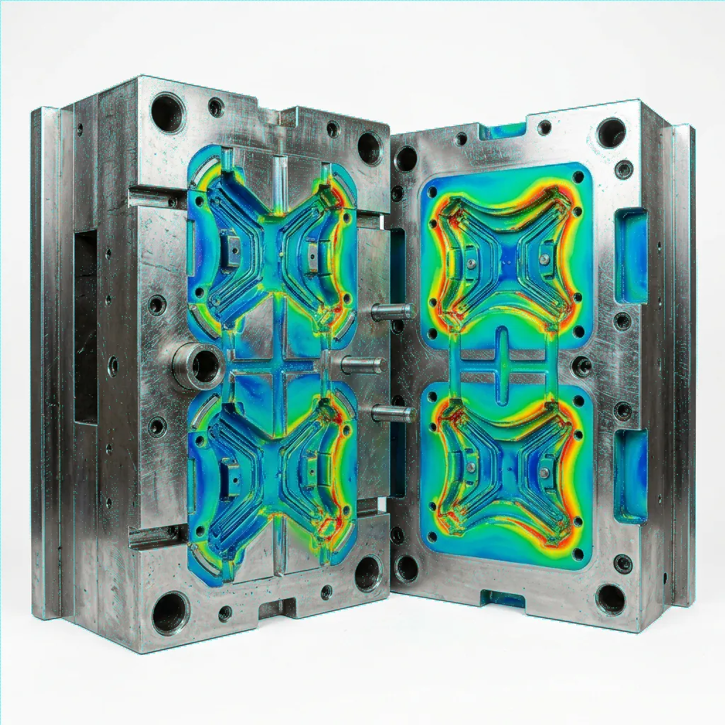
INJECTION MOULDING SIMULATION

Mould Flow Filling Analysis Services in India

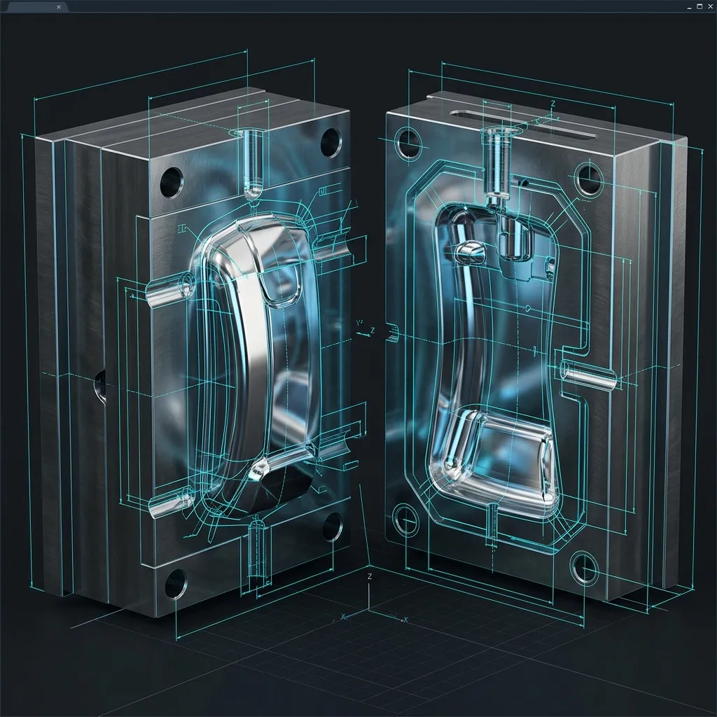
Visualize the molten polymer flow front before the tool exists. Optimize gate locations, prevent weld lines, and eliminate air traps with advanced injection moulding simulation services.

One Gate. Three Outcomes.

Hover over the injection nodes to see why simulation matters before tool steel is cut. Watch the flow front react instantly.
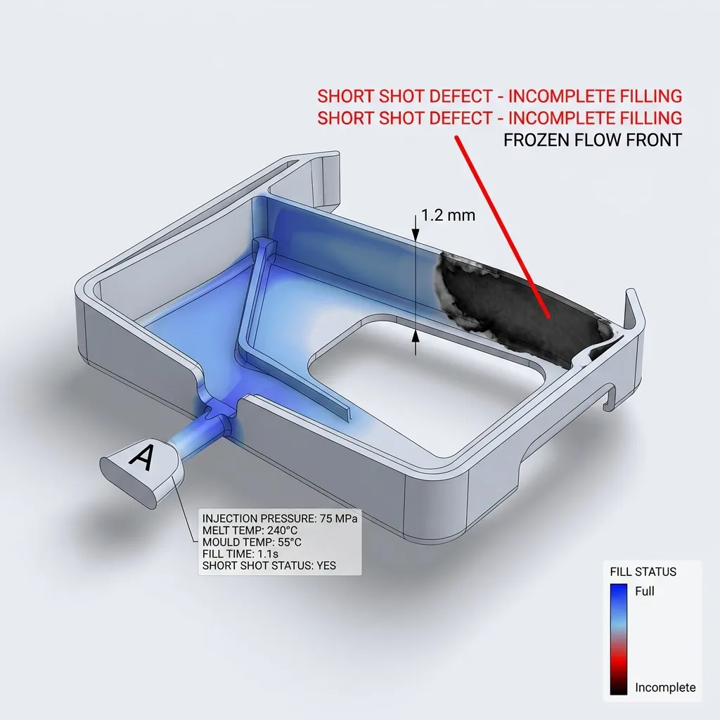
Gate Position A
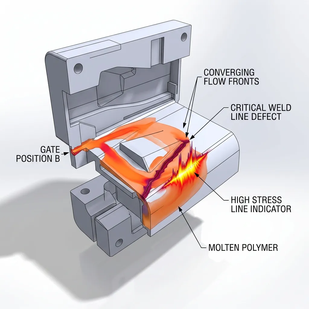
Gate Position B
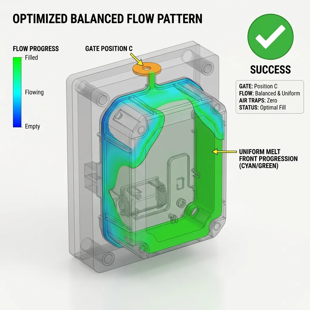
Gate Position C
Optimized Gate Preview
Hover Nodes to Test Gates
Short Shot Defect
Gate A: Incomplete Short Shot
Weld Line Defect
Gate B: Critical Weld Line
Optimized Flow
Gate C: Balanced Optimal Filling

Defect Diagnostics

Hover over a defect
point to diagnose.

Short Shot Risk

Incomplete plastic fill defect where the cavity is not fully packed, often caused by inadequate pressure.

Weld Lines

A critical structural weakness caused by two or more flow fronts meeting and failing to fuse completely.

Air Traps

Pockets of air compressed inside the cavity that cannot escape, leading to unsightly burn marks or voids.

Sink Marks

Shallow surface depressions caused by uneven cooling and localized volumetric shrinkage in thicker sections.

Hesitation Zones

Thin wall areas where the polymer flow stalls or drastically slows down, causing premature freezing.

Race Tracking

Uneven flow progression where molten polymer rushes through thicker sections, trapping air in thinner areas.

Short Shot Risk
Weld Lines
Air Traps
Sink Marks
Hesitation Zones
Race Tracking

Digital Polymer Journey

What the filling simulation covers, step by step.

1. Gate Entry

Initial shear and injection pressure analysis.

2. Flow Front

Melt progression tracking.

3. Cavity Fill

Volumetric filling speed validation.

4. Weld Line

Knit line formation prediction.

5. Air Displacement

Venting layout optimization.

6. Complete Fill

Final pressure & V/P switchover.
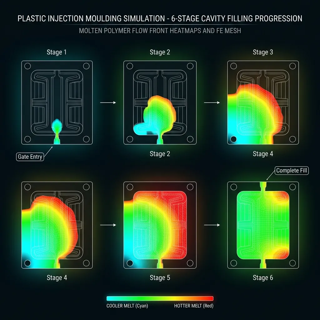
6-Stage Cavity Fill Progression Sequence

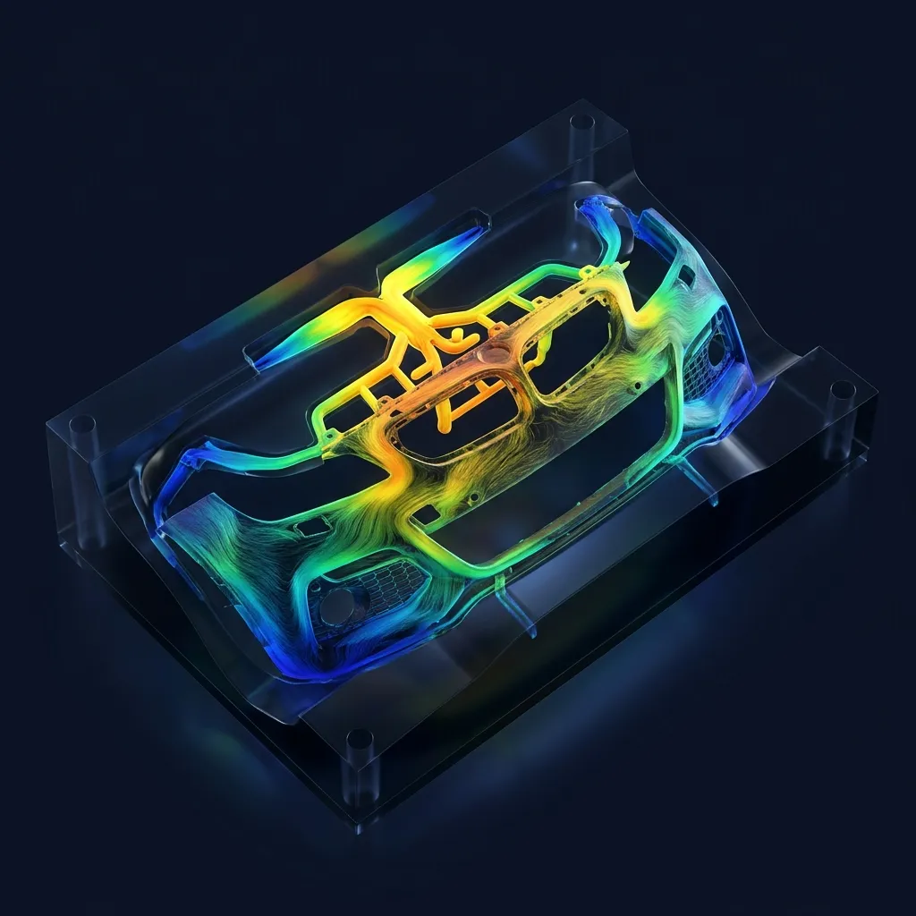
Geometries Where
Simulation Matters Most
Engineering Report Dashboard

Simulation Outputs & Deliverables

Tooling Optimization Loop

Production-Ready
Tool Design

1. Receive CAD
2. Setup
3. Flow Analysis
4. Defect Detection
5. Modification
6. Validation

Mould Warpage & Shrinkage

Post-fill structural analysis →

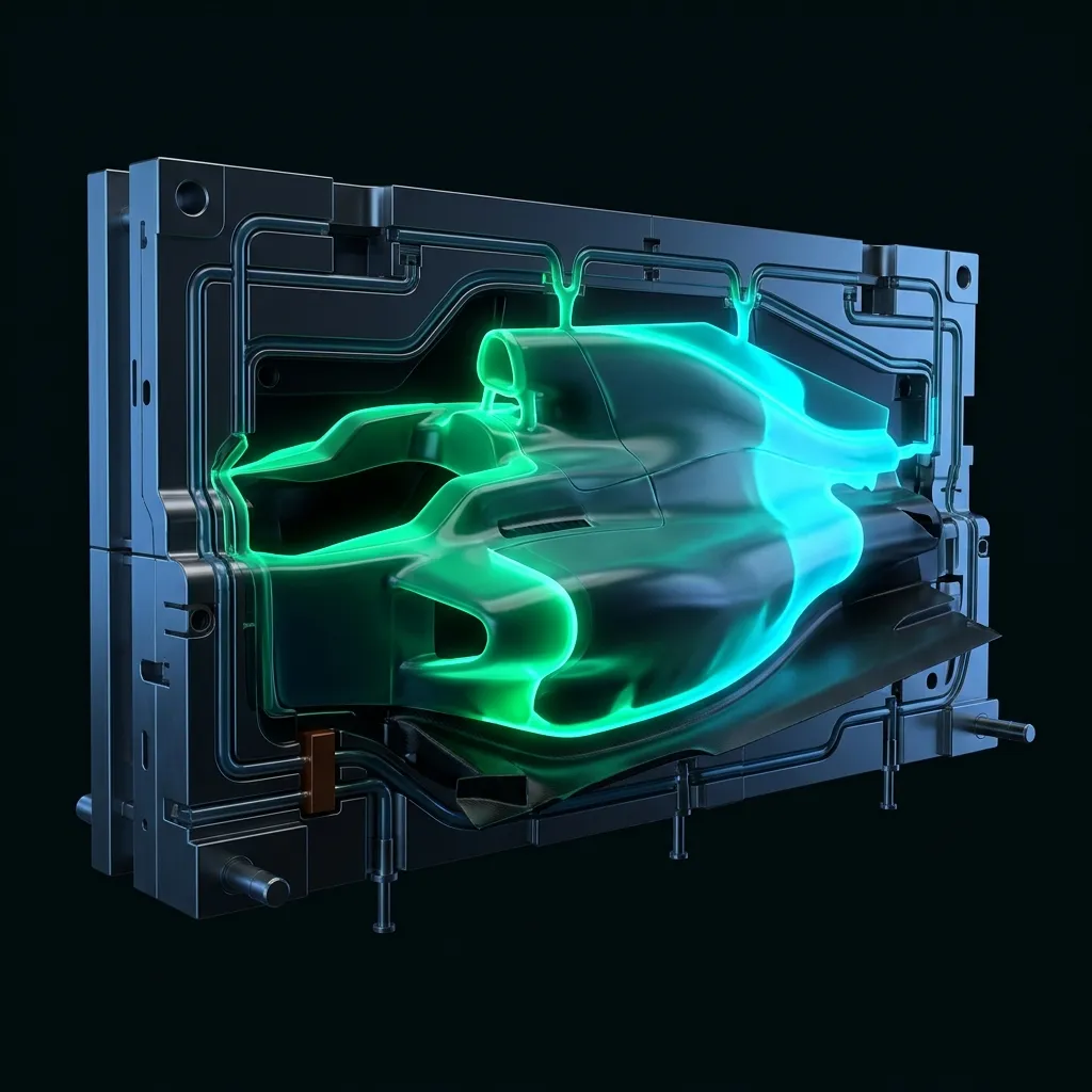
CFD Flow Simulation

Fluid dynamics services →

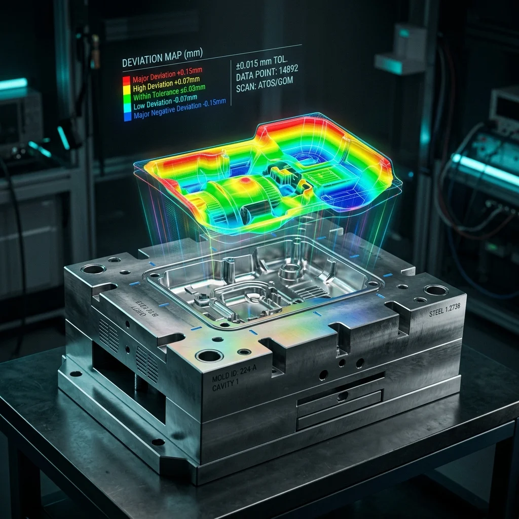
3D Scanning for Plastics

Physical tool validation →

Technical Service Overview Reviewed by APJ 3D Engineering Desk • Updated September 2026

What is Mould Flow Filling Analysis Services India?

CAE Simulation (FEA & CFD) is the numerical modeling of physical systems to predict structural stress, thermal dissipation, fluid flow, crashworthiness, and dynamic fatigue life under real-world operational loads.

When to Select This Service

Choose CAE simulation during early product development to virtually validate design integrity, optimize part weight, verify safety factors, and eliminate physical prototype failure risks before committing to production tooling.

Mould Flow Filling Analysis Services India Technical Specifications

Technical Capabilities & Verification Standards

Verified engineering parameters, hardware precision, and compliance benchmarks applied across all deliverables.

Engineering Parameter APJ 3D Capability & Precision Range Compliance Standard / Verification
Simulation Disciplines Linear/Non-Linear Structural FEA, Thermal Analysis, CFD Fluid Dynamics, Crash & Impact, Fatigue & Durability, NVH ISO 9001 / NAFEMS Validated Procedures
Solvers & Software ANSYS Mechanical, Abaqus, Altair HyperWorks/OptiStruct, Moldflow, OpenFOAM, LS-DYNA High-Performance Computing (HPC) Clusters
Material Models Elastic-Plastic metals, Hyperelastic rubbers, Composites, Viscoelastic polymers, Temperature-dependent curves Tested Material Property Databases
Mould Flow Capabilities Fill time, injection pressure, weld line prediction, sink marks, cooling circuit efficiency, volumetric shrinkage & warpage Autodesk Moldflow Insight Validated
Deliverables Comprehensive Engineering Reports, Von Mises Stress Plots, Factor of Safety (FoS) Maps, Deformation Animations, Optimization STEPs Actionable Design Recommendation Summaries
Model Scale From precision micromixers and plastic clips up to full vehicle chassis and industrial equipment weldments Multi-Million Degree-of-Freedom Meshes
Turnaround Time 3 to 7 business days for standard FEA/CFD studies; 24–48h for urgent gate location & fill checks Dedicated Senior CAE Analysts
FAQ

Frequently Asked Questions

What information is required to start an FEA or CFD simulation?

We need 3D CAD files (STEP/Parasolid), material specifications, operating boundary conditions (forces, pressures, temperatures, constraints), and load cases (static, cyclic, or dynamic impact).

How do you validate the accuracy of simulation results?

We follow NAFEMS simulation guidelines, perform mesh convergence sensitivity studies, apply realistic physical contact formulations, and correlate models against physical test data where available.

How can Moldflow simulation save tooling costs for plastic parts?

Moldflow identifies potential defects like air traps, weld lines in high-stress zones, short shots, and excessive warpage before cutting tool steel, saving weeks of tool rework and thousands of dollars in tooling modifications.

Can you optimize parts for lightweighting and material reduction?

Yes. We perform topology optimization and parametric sizing to redistribute material according to principal stress trajectories, achieving 15% to 40% weight reduction while maintaining target safety factors.

What is included in the final simulation report?

The report provides an executive summary, methodology description, boundary condition diagrams, stress/strain/displacement distribution plots, safety factor evaluation, and clear design modification recommendations.

Validate Structural Safety for Your Products?

From Low-Speed Impacts to High-Energy Crashes — APJ 3D Delivers Accurate Crash and Impact Simulation Services Across India.