Engineering Services for Sheet Metal and Fabrication in India
Dimensional Control From First Article Inspection to Production Validation.
What Sheet Metal Engineering Services Does APJ 3D Provide?
Metrology, forming analysis, and weldment verification to control springback and distortion.
APJ 3D provides 3D inspection and CAD comparison, first article inspection (FAI) against PPAP requirements, ZEISS ARGUS springback and forming analysis, weldment assembly inspection, and reverse engineering for sheet metal and fabricated parts across India.
Sheet metal and fabricated parts rarely come off the line matching the CAD model. Springback, weld distortion, and dimensional variation between the first article and batch production are the recurring problems — APJ 3D's engineering services exist to measure, quantify, and correct them.
Dimensional Inspection
3D scanning and CAD comparison for stamped, formed, and fabricated parts, plus first article inspection (FAI) that documents Level 3 PPAP submissions with full-surface GD&T reporting to ASME Y14.5 — typically 50-150+ characteristics per part — instead of a handful of CMM points. Standard turnaround is 24-48 hours from scan to signed-off report.
Springback & Forming Analysis
ZEISS ARGUS optical forming analysis measures major/minor strain against the forming limit curve (FLC) and quantifies springback angle deviation — often 1-5° on high-strength steel and AHSS grades — plus thinning percentage at radii and flanges, the data die makers need to correct tool geometry before it turns into a batch of rejects.
Weldment & Assembly Correction
Weld distortion analysis (angular distortion, longitudinal shrinkage, and out-of-flatness after fixture release) and datum shift calculations for fabricated assemblies against AWS D1.1 / customer weld schedules, plus reverse engineering of legacy tooling and parts with no usable CAD data, output to STEP or native SolidWorks within 3-5 working days depending on part count.
Sheet Metal Has a Mind of Its Own —
The Data to Manage It Changes Everything
Sheet metal deviates from CAD at every stage of the process — forming introduces springback, welding introduces distortion, and assembly stacks both errors together. Measuring where deviation begins is what keeps a batch of parts in tolerance.
Design CAD
Forming
Springback
Weld Distortion
Assembly Issues
Production Delays
Know exactly where dimensional variation begins.
Stop the GuessworkWhat We Do for
Sheet Metal and Fabrication
Our complete dimensional control workflow provides a unified approach to measuring, analyzing, and improving your sheet metal components and fabricated assemblies from start to finish.
3D Inspection
First Article Inspection
ZEISS ARGUS
Weldment Inspection
Reverse Engineering
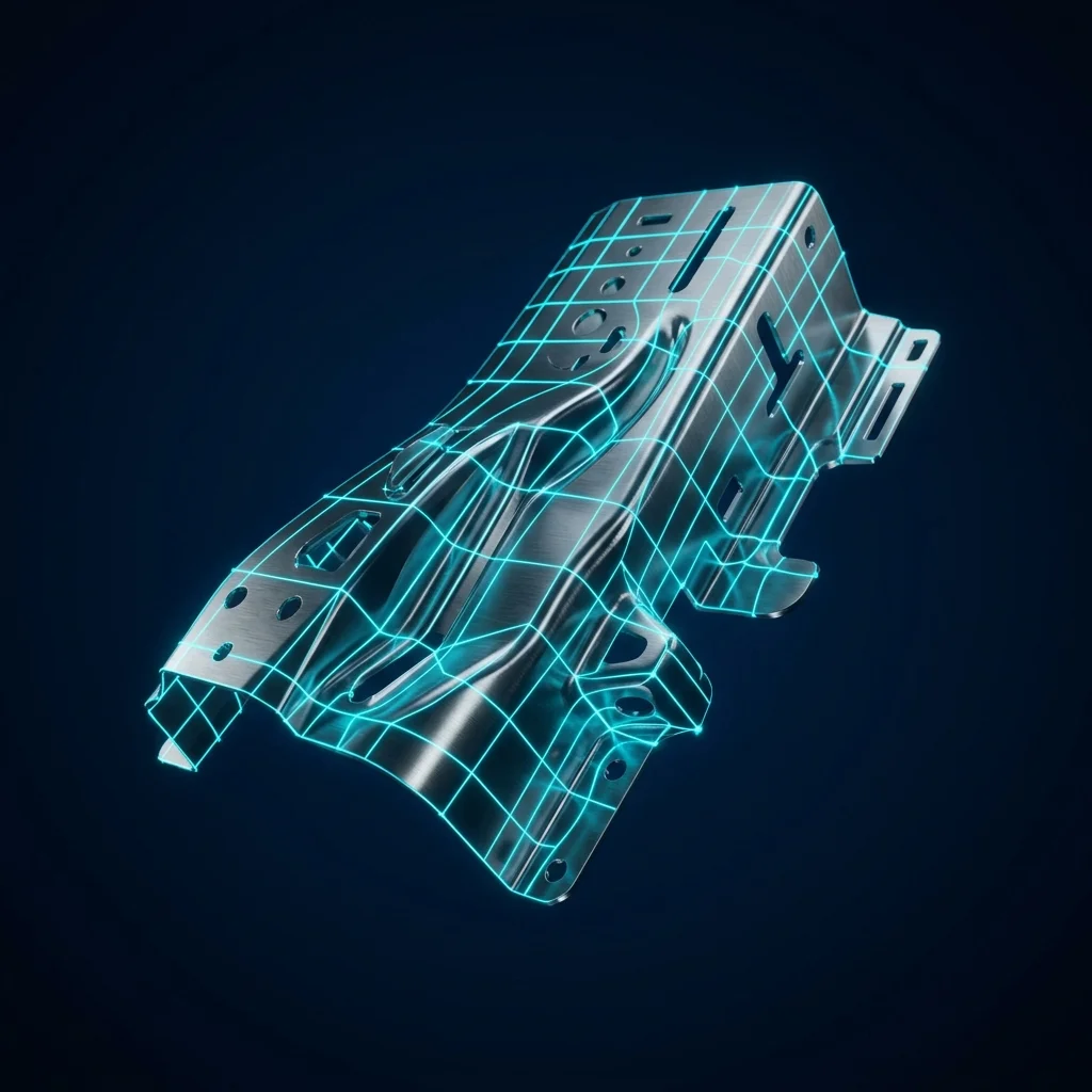
3D Inspection for Sheet Metal
- Full surface inspection
- CAD comparison & GD&T reporting
- ZEISS GOM Scan 1 & Creaform
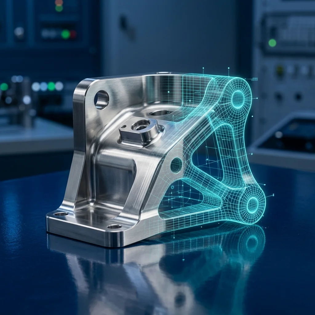
First Article Inspection
- OEM submission reports
- Batch inspection tracking
- Supplier qualification data

Springback and Forming Analysis — ZEISS ARGUS
- Forming limit analysis
- Material thinning & strain
- Springback measurement
- Tooling optimization loop
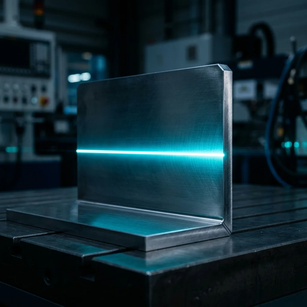
Weldment Assembly Inspection
- Weld distortion analysis
- Datum shift calculations
- Portable metrology on-site
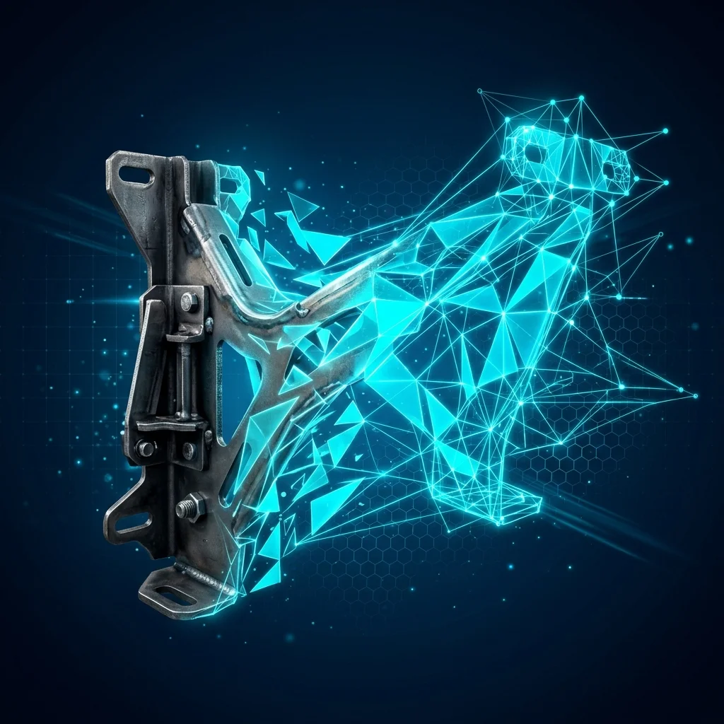
Reverse Engineering
- Output to STEP / SolidWorks
- Legacy tooling recreation
- Digital design modifications
From Scan Data to
Production Decisions
Integrating 3D inspection, springback analysis, and first article inspection directly into your sheet metal fabrication workflow.
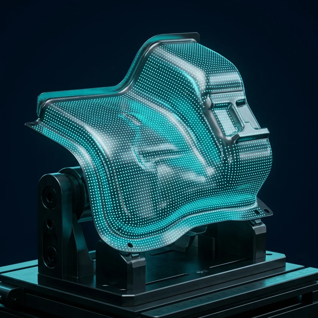
ZEISS ARGUS Forming Analysis
One of the Most Specialized Sheet Metal Engineering Capabilities Available in India
Springback and material thinning are the enemies of high-volume sheet metal production. Our optical forming analysis captures full-field strain distribution and validates your forming simulation with real-world tryout data, complementing first article inspection and weldment inspection once the part moves into assembly.
-
Material thinning analysisIdentify necking and failure risks before production.
-
Forming limit measurementValidate against FLC (Forming Limit Curve).
-
Springback evaluationQuantify elastic recovery to compensate tool geometries.
-
Tool correction guidanceProvide exact deviation metrics for die makers.
-
Scrap reductionMinimize material waste and rework.
ZEISS ARGUS Forming Analysis vs. Traditional Strain Gauge Measurement
Both methods measure strain on a formed part, but they differ in coverage and speed. Traditional strain-gauge and circle-grid methods sample a handful of fixed points on the panel; ZEISS ARGUS optical forming analysis captures full-field strain across the entire surface in one pass, which is why it has become the preferred validation method for stamping tryout and simulation correlation.
- Measures strain at a limited number of pre-etched circle-grid points, usually 20-50 locations per panel
- Manual grid measurement per point — several hours per part for a full panel
- Blind spots between grid points can hide localized necking or tearing risk
- Difficult to correlate directly against a forming simulation mesh
- Point data alone gives little guidance on tool correction direction or magnitude
- Captures full-field major/minor strain across the entire part surface — millions of data points, no gaps
- Complete part measured in under an hour, with results available the same day
- Plots every measured point against the forming limit curve (FLC), flagging thinning and tearing risk anywhere on the surface
- Directly overlays onto forming simulation results for tool-vs-simulation correlation
- Deviation and springback maps translate into specific, localized tool correction data for the die maker
Engineering Value for
Sheet Metal Production
Reduce Scrap
Identify material tearing and thinning risks early using optical strain measurement, drastically reducing scrap rates during mass production.
Improve Tool Accuracy
Provide precise deviation color maps to your toolmakers so they can correct dies faster and with pinpoint accuracy.
Accelerate Supplier Approval
Our first article inspection service for sheet metal components ensures your PPAP submissions are robust, objective, and accepted immediately.
Control Weld Distortion
Track datum shifts and twisting across large fabricated assemblies to define proper welding sequences and fixture clamping strategies.
Validate First Articles Faster
Digitize complex organic sheet metal surfaces entirely in minutes, bypassing the limitations of traditional point-by-point CMM probing.
Improve Production Consistency
Lock in your processes using dimensional data, ensuring that batch 1000 holds the exact same tolerances as batch 1.
The Metrology Partner You Can Trust
What is Sheet Metal Fabrication Engineering Services India?
Sheet metal fabrication engineering covers the dimensional control and validation activities that support production of formed and stamped metal parts, including First Article Inspection (FAI), production part validation, and CAD-to-part comparison for tooling and stamped components manufactured across the sheet metal industry.
When to Select This Service
Choose sheet metal fabrication engineering support when you need dimensional control from first article inspection through production validation, or when stamped and formed components must be verified against master CAD before scale-up.
Technical Capabilities & Verification Standards
Verified engineering parameters, hardware precision, and compliance benchmarks applied across all deliverables.
| Engineering Parameter | APJ 3D Capability & Precision Range | Compliance Standard / Verification |
|---|---|---|
| Dimensional Inspection | 3D scan-based dimensional checks of stamped, formed, and fabricated sheet metal parts against master CAD | Colour Deviation Mapping |
| Springback & Forming Analysis | Simulation and scan-based correlation of springback and forming behaviour using ZEISS ARGUS strain analysis | ZEISS ARGUS Correlation |
| Weldment & Assembly Correction | Identification and correction of weld distortion and assembly-stage dimensional drift | Weldment Assembly Inspection |
| First Article Inspection | Full dimensional sign-off on initial production parts before supplier approval and volume production | Supplier Approval Support |
| Reverse Engineering | Point-cloud to CAD reconstruction for legacy tooling and fabricated components without native CAD data | Point Cloud to CAD |
| Industry Coverage | Dimensional control programs spanning automotive and aerospace sheet metal and fabrication production lines | Pan-India On-Site Mobilization |
Frequently Asked Questions
Can you perform 3D scanning on-site at our manufacturing plant?
Can you perform 3D scanning on-site at our manufacturing plant?
How do 3D scanning and reverse engineering differ?
How do 3D scanning and reverse engineering differ?
What is a color deviation inspection map?
What is a color deviation inspection map?
Can dark, shiny, or transparent surfaces be scanned?
Can dark, shiny, or transparent surfaces be scanned?
What accuracy can we expect for automotive and aerospace components?
What accuracy can we expect for automotive and aerospace components?
Eliminate Springback & Weld Distortion — For Good
From first-off scanning to full-run forming analysis, APJ3D helps sheet metal fabricators catch dimensional deviations, correct tooling, and deliver conforming parts — faster.