Prevent Overheating Before The First Prototype
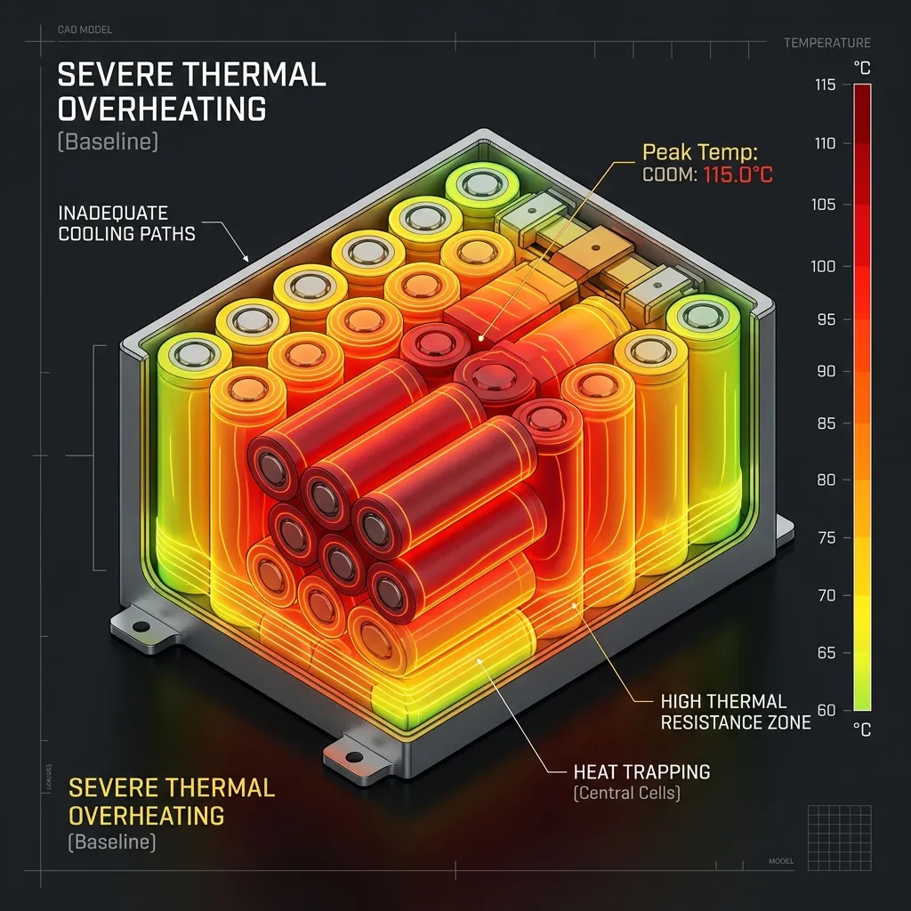
Visualize unseen heat flow, optimize thermal management, and prevent catastrophic failures. Our Thermal Analysis Services and Steady State & Transient FEA provide complete thermal visibility for industrial and electronic components.
Heat Failures Don't Announce Themselves Early
A minor hotspot in design becomes a massive warranty claim in the field. Visualizing thermal stress analysis early prevents the domino effect of failure.
Unnoticed Hotspots
Compact enclosures create restricted airflow. Without simulation, internal component temperatures remain an educated guess.
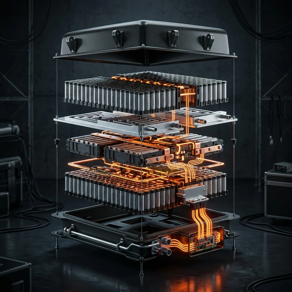
Material Warpage
Physical prototypes subjected to operational loads begin to show early signs of thermal expansion and geometric deviation.
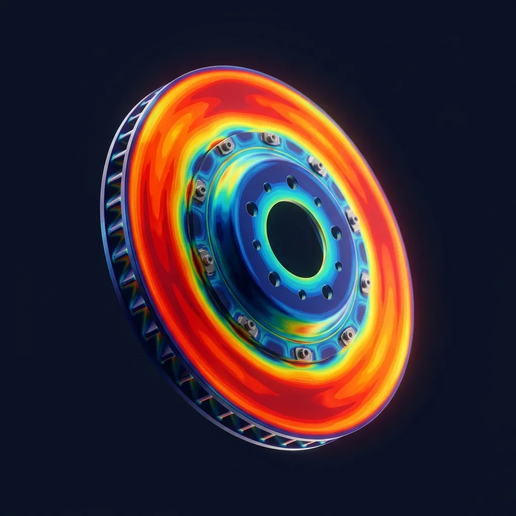
Solder Joint Fatigue
Thermal cycling stress induces micro-fractures in electronic PCB solder joints, leading to intermittent signal failures.
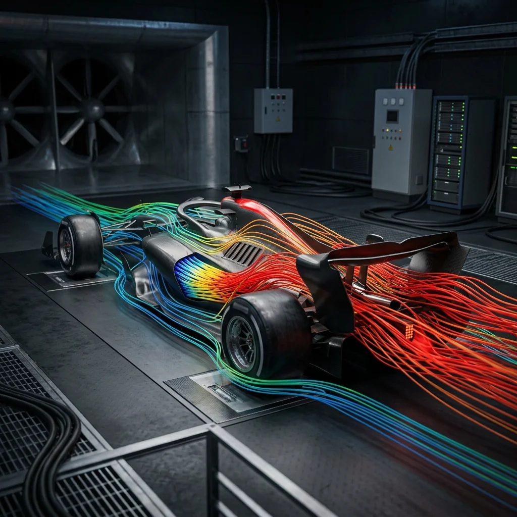
Housing Deformation
Prolonged steady-state heat causes permanent plastic deformation, compromising IP ratings and structural integrity.
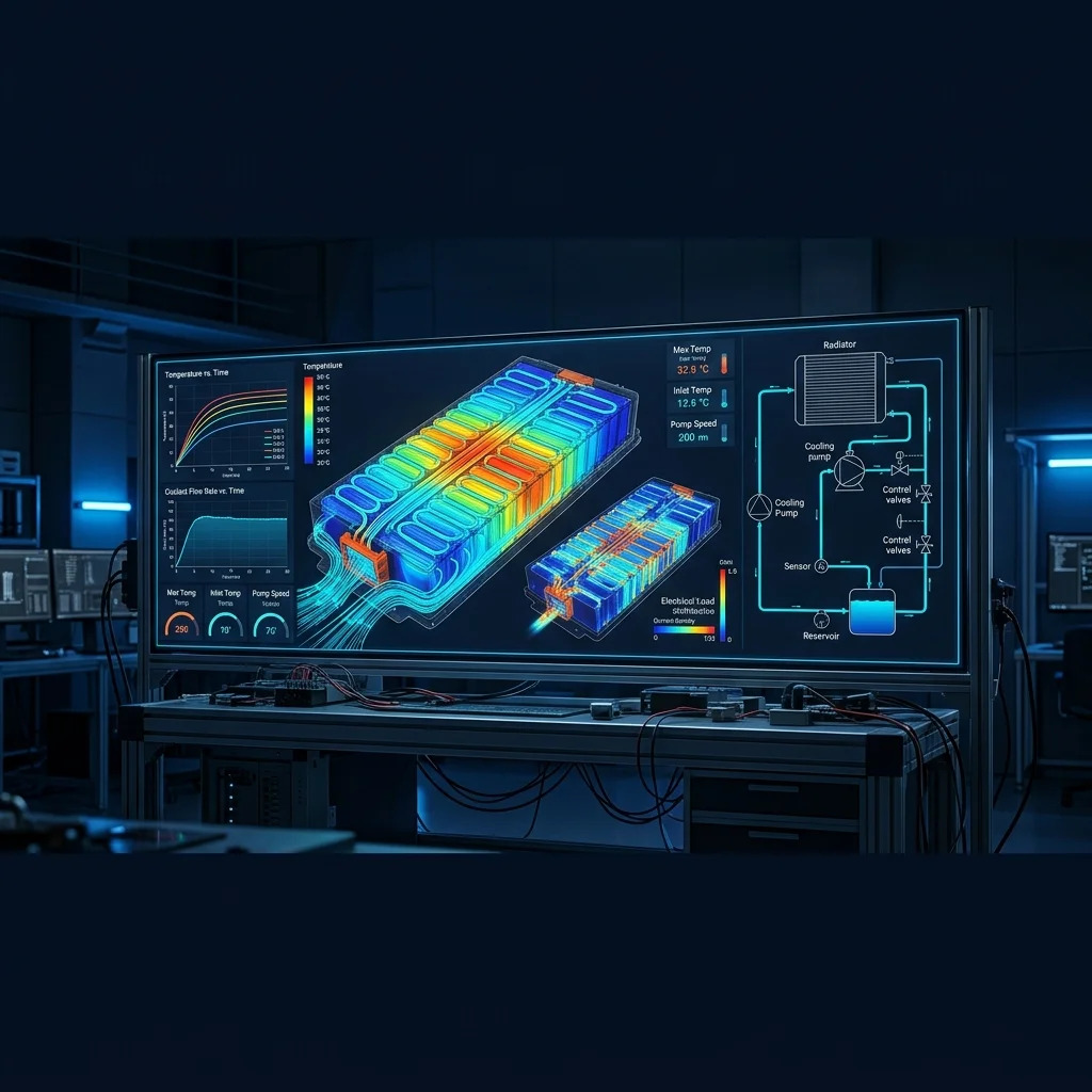
Warranty Recalls
Premature lifecycle failure results in brand damage, massive recall logistics, and severe financial warranty penalties.
The 3D Heat Transfer Ecosystem
Our heat transfer analysis service for industrial design India captures all three fundamental modes of thermodynamics simultaneously, creating a perfect digital twin of your thermal environment.
Conduction Mapping
Analyzing internal heat flow through solid materials. Identifying thermal bottlenecks, evaluating heat sinks, and optimizing material thickness for maximum heat dissipation.
Convection Analysis
Evaluating heat transfer between solid surfaces and surrounding fluids (air/liquid). We model natural buoyancy effects and forced airflow from cooling fans in complex enclosures.
Radiation Emission
Crucial for high-temperature applications or space environments. Simulating electromagnetic heat emission and the effect of surface emissivity, coatings, and adjacent thermal masses.
Delivering a complete thermal simulation service for electronics and automotive India by combining all physical phenomena into one precise mathematical model.
Engineering Comparison Lab
Choose the right mathematical approach. APJ 3D provides both steady state and transient thermal FEA services India depending on your product's duty cycle.
Steady State Thermal FEA
Calculates the thermal equilibrium. Predicts the final temperatures and heat fluxes when operating conditions remain constant over an infinite period.
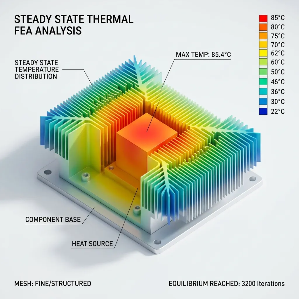
- Evaluates absolute maximum operating temperatures
- Identifies permanent thermal bottlenecks
- Ideal for continuous-duty electronics & heat sinks
- Faster computation for rapid design iterations
Transient Thermal FEA
Time-dependent simulation. Evaluates how temperatures fluctuate over time during power cycling, startup spikes, and intermittent loading.

- Captures thermal shock and sudden temperature spikes
- Models heating/cooling rates and duty cycles
- Essential for automotive brakes, engine startup, electronics switching
- Inputs for calculating thermal fatigue lifespan
Thermal Applications Matrix
Cross-industry expertise. We solve specific thermodynamic challenges whether it’s micro-electronics or heavy industrial machinery.
Interactive Deliverables Dashboard
See exactly what you get. Our reports bridge the gap between complex thermodynamics and actionable mechanical design improvements.

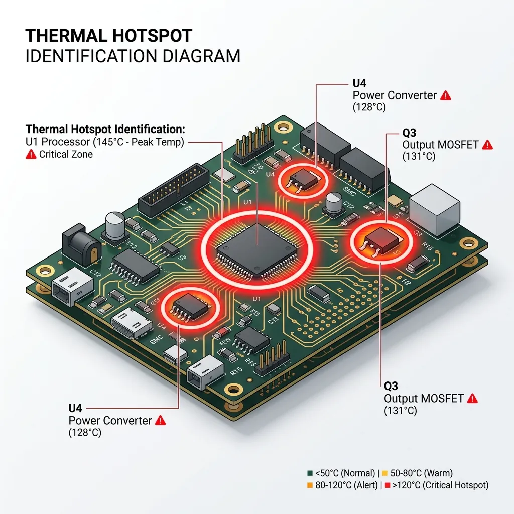


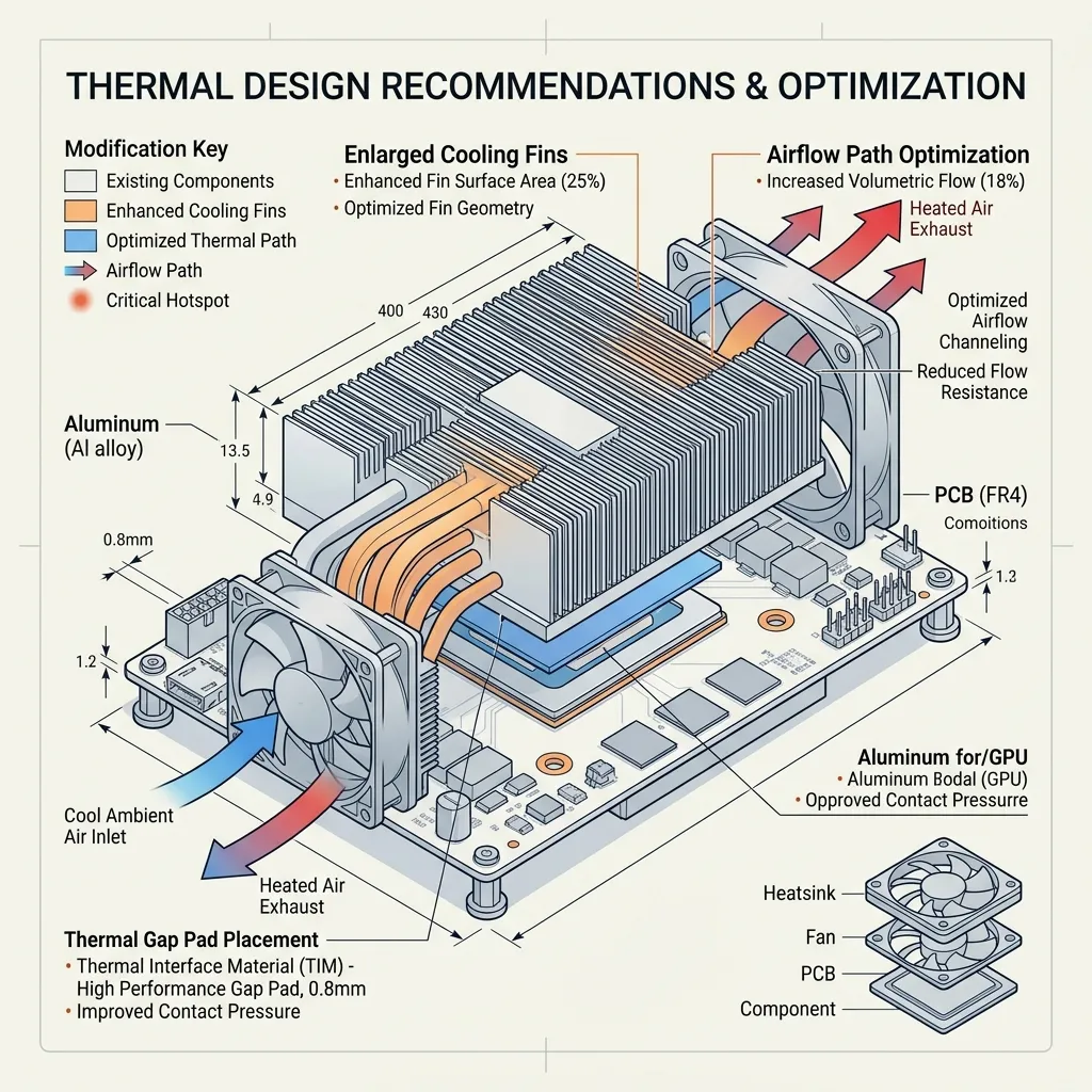
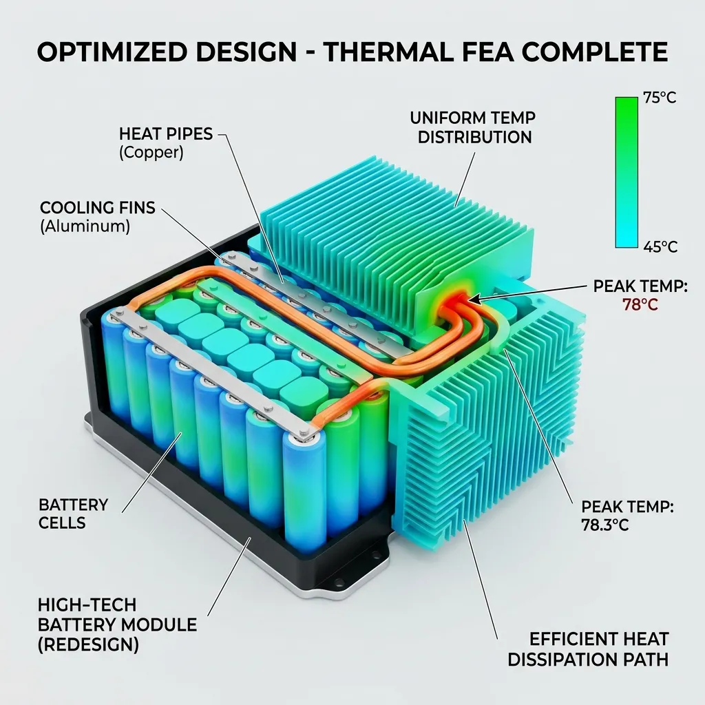
Iterative Design Optimization
We don't just point out problems. Drag the slider to see how our iterative loop transforms thermal failures into validated designs ready for manufacturing.
What is Thermal Analysis & Heat Transfer Simulation India?
CAE Simulation (FEA & CFD) is the numerical modeling of physical systems to predict structural stress, thermal dissipation, fluid flow, crashworthiness, and dynamic fatigue life under real-world operational loads.
When to Select This Service
Choose CAE simulation during early product development to virtually validate design integrity, optimize part weight, verify safety factors, and eliminate physical prototype failure risks before committing to production tooling.
Technical Capabilities & Verification Standards
Verified engineering parameters, hardware precision, and compliance benchmarks applied across all deliverables.
| Engineering Parameter | APJ 3D Capability & Precision Range | Compliance Standard / Verification |
|---|---|---|
| Simulation Disciplines | Linear/Non-Linear Structural FEA, Thermal Analysis, CFD Fluid Dynamics, Crash & Impact, Fatigue & Durability, NVH | ISO 9001 / NAFEMS Validated Procedures |
| Solvers & Software | ANSYS Mechanical, Abaqus, Altair HyperWorks/OptiStruct, Moldflow, OpenFOAM, LS-DYNA | High-Performance Computing (HPC) Clusters |
| Material Models | Elastic-Plastic metals, Hyperelastic rubbers, Composites, Viscoelastic polymers, Temperature-dependent curves | Tested Material Property Databases |
| Mould Flow Capabilities | Fill time, injection pressure, weld line prediction, sink marks, cooling circuit efficiency, volumetric shrinkage & warpage | Autodesk Moldflow Insight Validated |
| Deliverables | Comprehensive Engineering Reports, Von Mises Stress Plots, Factor of Safety (FoS) Maps, Deformation Animations, Optimization STEPs | Actionable Design Recommendation Summaries |
| Model Scale | From precision micromixers and plastic clips up to full vehicle chassis and industrial equipment weldments | Multi-Million Degree-of-Freedom Meshes |
| Turnaround Time | 3 to 7 business days for standard FEA/CFD studies; 24–48h for urgent gate location & fill checks | Dedicated Senior CAE Analysts |
Frequently Asked Questions
What information is required to start an FEA or CFD simulation?
What information is required to start an FEA or CFD simulation?
How do you validate the accuracy of simulation results?
How do you validate the accuracy of simulation results?
How can Moldflow simulation save tooling costs for plastic parts?
How can Moldflow simulation save tooling costs for plastic parts?
Can you optimize parts for lightweighting and material reduction?
Can you optimize parts for lightweighting and material reduction?
What is included in the final simulation report?
What is included in the final simulation report?
Solve Heat Dissipation Issues for Your Designs?
From Electronics Cooling to Extreme Heat Shields — APJ 3D Delivers Advanced Thermal Analysis Services Across India.