Digital Reconstruction Service for Manufacturing Parts India
We recover lost engineering knowledge from physical assets. 3D Digital Reconstruction, Mesh to CAD Conversion, and Reverse Engineering for Production and Tooling Documentation.
When the Physical Part Is the Only Record That Exists
What Digital Reconstruction Actually Requires
And Why Mesh Conversion Isn't Enough
Mesh (.STL / .OBJ)
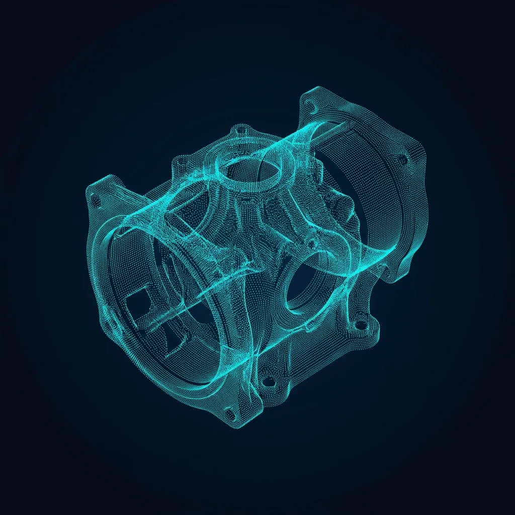
- Polygon data only
- Non-editable geometry
- Inspection reference only
- No feature history
Parametric CAD (.STEP / .IGES)
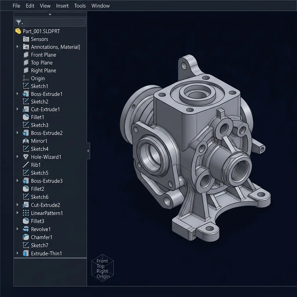
- Editable feature tree
- CAM / CNC ready
- FEA / Simulation ready
- 2D Drawing ready
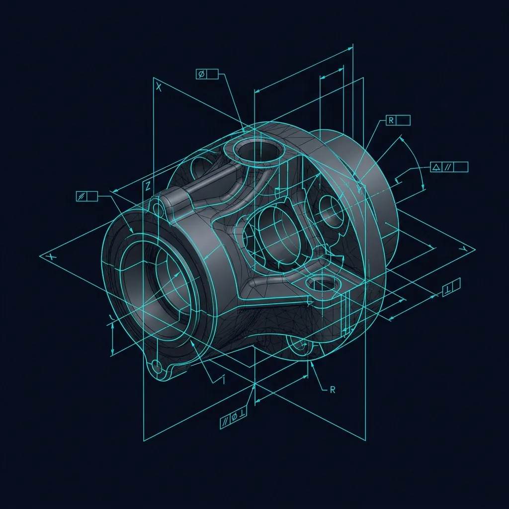
Mesh to CAD Reconstruction Service India
Industries Using Digital Reconstruction
Automotive Components
Challenge: Recovering Class-A surfaces and obsolete engine castings.
Deliverable: Fully parametric CATIA/NX models ready for PPAP.
Aerospace Parts
Challenge: Traceable MRO digitisation of turbine blades and aerofoils.
Deliverable: High-accuracy NURBS surface models with deviation reports.
Foundry & Casting
Challenge: Rebuilding damaged wooden patterns and worn metal dies.
Deliverable: Shrinkage-compensated 3D CAD patterns for sand printing/machining.
Plastics & Moulding
Challenge: Correcting mould cavities after manual polishing and tuning.
Deliverable: 'As-Built' CAD updates reflecting physical mould modifications.
Heavy Engineering
Challenge: Digitising massive earthmoving linkages and mining equipment without original drawings.
Deliverable: Assembly-level CAD and 2D manufacturing drawings.
Tool Rooms
Challenge: Replacing broken inserts or jigs where the designer has left.
Deliverable: Exact replica CAD models with GD&T extraction.
3D Reconstruction Service for Casting and Moulding India
LEFT PATH: Product First
When only the finished component exists.
RIGHT PATH: Tool First
When the mould or die needs modification.
The APJ 3D Advantage & Deliverables
Why Manufacturers Choose Us
What You Receive
What is Digital Reconstruction Services for Manufacturing?
Digital Reconstruction is the recovery of lost engineering knowledge from physical assets, converting 3D scan meshes and point clouds into editable parametric CAD models and production or tooling documentation for parts that have no surviving digital record.
When to Select This Service
Choose digital reconstruction when production or tooling documentation has been lost, when legacy manufacturing parts need to be rebuilt into usable CAD, or when a mesh-to-CAD conversion is needed to restore an editable design record.
Technical Capabilities & Verification Standards
Verified engineering parameters, hardware precision, and compliance benchmarks applied across all deliverables.
| Engineering Parameter | APJ 3D Capability & Precision Range | Compliance Standard / Verification |
|---|---|---|
| Reconstruction Techniques | Parametric Feature Modeling, Hybrid Surface-Solid Modeling, Class-A B-Rep Surfacing | Design Intent Extraction |
| Scan-to-CAD Deviation | Surface deviation within ±0.025 mm to ±0.050 mm of scan data (Geometry dependent) | Geomagic Design X / Geomagic Control X |
| Supported Part Types | Castings, forgings, stampings, injection molded plastics, turbine blades, automotive body panels, tooling dies | Micron to Multi-Meter Scale |
| Output Formats | Native SolidWorks (.sldprt), Siemens NX (.prt), CATIA (.CATPart), STEP (.stp), IGES (.igs), Parasolid (.x_t) | Fully Editable Feature Trees |
| Manufacturing Detailing | Draft angle optimization, wall thickness regularization, fillet reconstruction, GD&T 2D blueprints | DFM / Tooling Ready |
| Quality Assurance | 3D Color Map Scan-to-CAD overlay deviation report verifying geometric fidelity | 100% Deviation Inspected |
| Turnaround Time | 2 to 5 business days for standard complex mechanical components and assemblies | Pan-India On-Site 3D Scanning Available |
Frequently Asked Questions
What is the difference between raw scan data (STL) and a reverse engineered CAD model?
What is the difference between raw scan data (STL) and a reverse engineered CAD model?
How do you handle worn or damaged areas on physical parts?
How do you handle worn or damaged areas on physical parts?
Can you reverse engineer internal features that cannot be scanned optically?
Can you reverse engineer internal features that cannot be scanned optically?
Do the reverse engineered models come with native feature trees?
Do the reverse engineered models come with native feature trees?
How is accuracy validated before delivery?
How is accuracy validated before delivery?
Need to Digitize and Reconstruct Obsolete Components?
Tell us your component type, reconstruction goal, and required output format. We will deliver a highly accurate digital record for modern manufacturing.