Point Cloud to Verified Parametric CAD Model
Transform raw physical components and high-density scan files into fully editable, parametric CAD databases in SolidWorks, CATIA, and Siemens NX. We deliver metrology-certified engineering geometry using industry-leading ZEISS scanning systems.
When drawings do not exist, production cannot wait
What You Have
The Engineering Bottleneck
-
Physical Part Only Obsolete components with no manufacturer support.
-
No Native Blueprints 2D drawings are lost, damaged, or unavailable.
-
Inflexible Scan Data Raw mesh data that cannot be engineered or edited.
What You Need
The APJ 3D Deliverable
-
Editable Parametric Model Native SolidWorks/NX files with full feature history.
-
Manufacturing-Ready Geometry Optimized drafts, cylinders, and mounting planes.
-
Supplier Documentation Comprehensive GD&T drawings and standard STEP outputs.
Step-by-Step Point Cloud to CAD Transformation
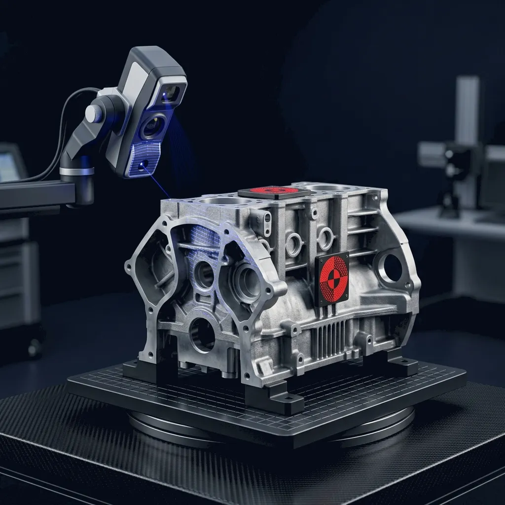
Physical Part
The physical component is cleaned and prepared for metrology-grade scanning.

3D Scan
Zeiss laser systems capture millions of coordinates representing geometry contours.

Point Cloud Data
Millions of coordinate points form a raw, uneditable polygon mesh representing the physical boundaries.

CAD Reconstruction
Features, cylinders, plane constraints and draft curves are extracted systematically.
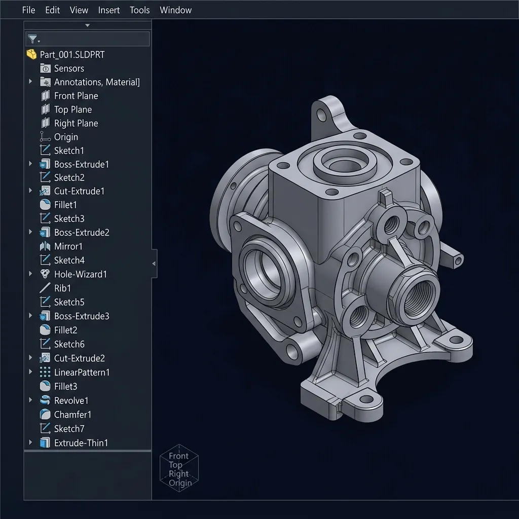
Parametric CAD
Final production-ready solid model containing native feature-history tree output.
The Three-Stage Scan to CAD Methodology
ZEISS T-Scan Hawk Metrology
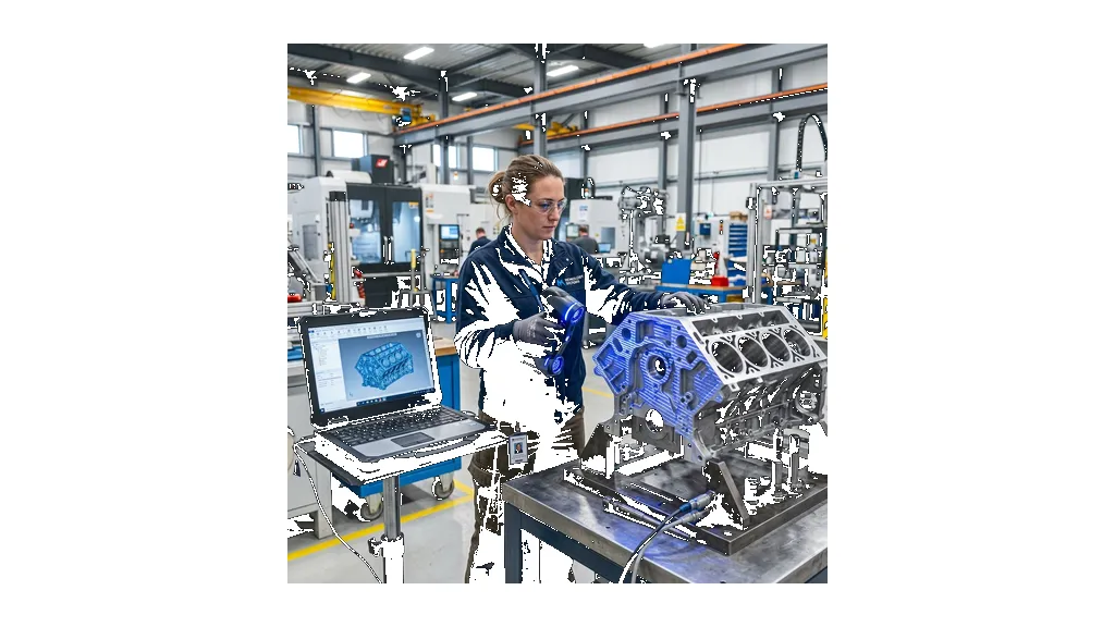
Geomagic Design X

SolidWorks / CATIA / Siemens NX

Deliverables Included with Every Scan to CAD Project
Parametric CAD Files
Fully structured models constructed with sketches, extrudes, revolutions, and features. Easy modifications directly in SolidWorks, CATIA, or Siemens NX.
Neutral CAD Exports
Supplier-ready universal files for immediate machining, tooling design, casting preparation, or manufacturing.
Traceable QA Records
Full documentation tracing scan alignments, volumetric measurements, and quality calibrations.
Color Deviation Reports
A comparative 3D inspection chart validating reconstructed CAD elements directly against raw metrology point cloud coordinates. Ensures nominal designs remain completely faithful to original components.
Engineering Drawings
Full 2D manufacturing sheets equipped with dimensional details, datum callouts, and GD&T requirements.
Restoring Production from a 20-Year-Old Cast Pattern

The Challenge
Worn Foundry Tooling with No CAD
An automotive casting supplier lost production capabilities when a critical engine block tooling die wore out. No technical drawings, specifications, or 3D models existed for the legacy foundry pattern.
The Solution
Metrology Scanning & Feature Re-align
We scanned the worn casting using the ZEISS T-Scan Hawk on-site. The raw mesh was aligned in Geomagic Design X, where we corrected drafts and rebuilt parametric features for native SolidWorks rendering.
The Results
Production line was restored 4 days ahead of scheduled timeline.
Seamless Integration with Your PLM/CAD Platforms
Metrology-Certified Quality Assurance Standards
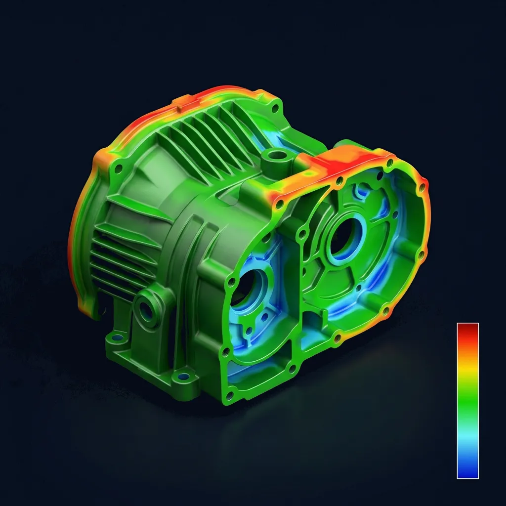
We bridge the gap between physical reality and digital precision. Every reconstructed CAD file is compared against the initial laser coordinates via a 3D deviation inspection. We confirm that all machined surfaces, key dimensions, and draft angles remain strictly within client-designated limits before shipping your files.
What is Scan to CAD Service India?
Scan to CAD is the conversion of raw 3D scan data, high-density point clouds and polygon meshes, into fully editable, metrology-certified parametric CAD models in SolidWorks, CATIA, or Siemens NX, rebuilding feature-based solid geometry from captured physical surfaces.
When to Select This Service
Choose scan to CAD when you have raw scan or point cloud data of a physical component and need a verified, editable parametric CAD database for redesign, tooling, or manufacturing rather than a static mesh.
Technical Capabilities & Verification Standards
Verified engineering parameters, hardware precision, and compliance benchmarks applied across all deliverables.
| Engineering Parameter | APJ 3D Capability & Precision Range | Compliance Standard / Verification |
|---|---|---|
| CAD Platforms | SolidWorks, Siemens NX, CATIA V5, Autodesk Inventor, Creo Parametric, AutoCAD | Native Feature Tree Formats |
| Drafting Standards | ASME Y14.5-2018, ISO 1101, ISO 128, DIN, JIS Standard Compliance | Full GD&T Tolerancing & Datums |
| Specialized Modeling | Class-A Surfacing, Complex Sheet Metal Flattening, Plastic Part Tooling DFM, Heavy Weldment Structures | Manufacturing-Ready Geometry |
| Drawing Deliverables | Fully Dimensioned 2D PDFs, DWG/DXF Flat Patterns, STEP AP242, Parasolid (.x_t), Native CAD Packages | Production-Ready Shop Blueprints |
| BOM & Documentation | Automated Hierarchical BOMs, Ballooned Assembly Drawings, Exploded Service Manuals, Hardware Catalogs | ERP-Ready Part Numbering |
| Quality Verification | Independent Senior Checker Review, Tolerance Stack-up Analysis, Interference & Clearance Checks | Zero-Defect Drafting Protocol |
| Turnaround Time | 24 to 72 hours for standard manufacturing drawing packages and CAD conversions | Scalable Dedicated Engineering Teams |
Frequently Asked Questions
Can you convert legacy 2D paper drawings or PDFs into 3D CAD models?
Can you convert legacy 2D paper drawings or PDFs into 3D CAD models?
Do your 2D engineering drawings include full GD&T callouts?
Do your 2D engineering drawings include full GD&T callouts?
How do you ensure sheet metal flat patterns account for bend allowances?
How do you ensure sheet metal flat patterns account for bend allowances?
Can you provide exploded views and assembly manuals for technical documentation?
Can you provide exploded views and assembly manuals for technical documentation?
What is the process for reviewing and revising drawing packages?
What is the process for reviewing and revising drawing packages?
Have a Physical Part but No CAD Model?
Get a verified parametric CAD model delivered in SolidWorks, CATIA or Siemens NX with documented accuracy and production-ready geometry.