Engineering Services for
Tool & Die Manufacturers in India
Precision tooling requires precision data. APJ 3D delivers 3D scanning, tool wear analysis, reverse engineering, CAD documentation, and portable CMM inspection services that help tool and die manufacturers validate, maintain, refurbish, and reproduce tooling with confidence throughout its lifecycle.
Engineering Support Built Around Tooling, Not Templates
Tool and die manufacturers work against tight tryout windows, wearing steel, and legacy tooling with no CAD trail. APJ 3D provides the metrology, simulation, and reverse engineering data that keeps that tooling accurate, repairable, and reproducible.
Mould Flow & Tolerance Analysis
Before steel is cut, mould flow filling and warpage/shrinkage simulation flags weld lines, air traps, and gate placement issues, while tolerance analysis stacks up cavity and core dimensions against the drawing so tryout doesn't surface avoidable defects.
Tool Validation & First Article Inspection
At T0/T1 tryout, 3D scanning and CMM measurement validate every cavity, insert, and parting line against nominal CAD, and first article inspection confirms the first production-representative parts meet drawing tolerances before a full run is committed.
Die/Mould Reverse Engineering
For worn or undocumented tools with no CAD on file, we scan the physical die or mould and rebuild it as a parametric, feature-based CAD model — correcting wear back to design intent so the tool can be refurbished, modified, or exactly reproduced.
Beyond new tool build, sheet metal forming analysis identifies splits, wrinkling, and springback risk in stamping dies before they reach the press, so panel-forming tools go into production with fewer die-tryout iterations. Combined with portable, shop-floor metrology for dies too large to move, these services cover the full tooling lifecycle — from concept validation through mid-life wear tracking to end-of-life reproduction — without forcing a tool out of production for inspection.
Mould Flow Simulation vs. Trial-and-Error Tool Tryout
Before steel is cut, a mould builder has two ways to find out whether a cavity design will actually work: run mould flow filling simulation on the CAD model first, or cut the tool and find out at T0 tryout. The gap between those two paths is measured in tryout iterations and machined steel, not just time.
Visualizing The Unseen
High-fidelity data capture reveals exactly what is happening on your tool surfaces.
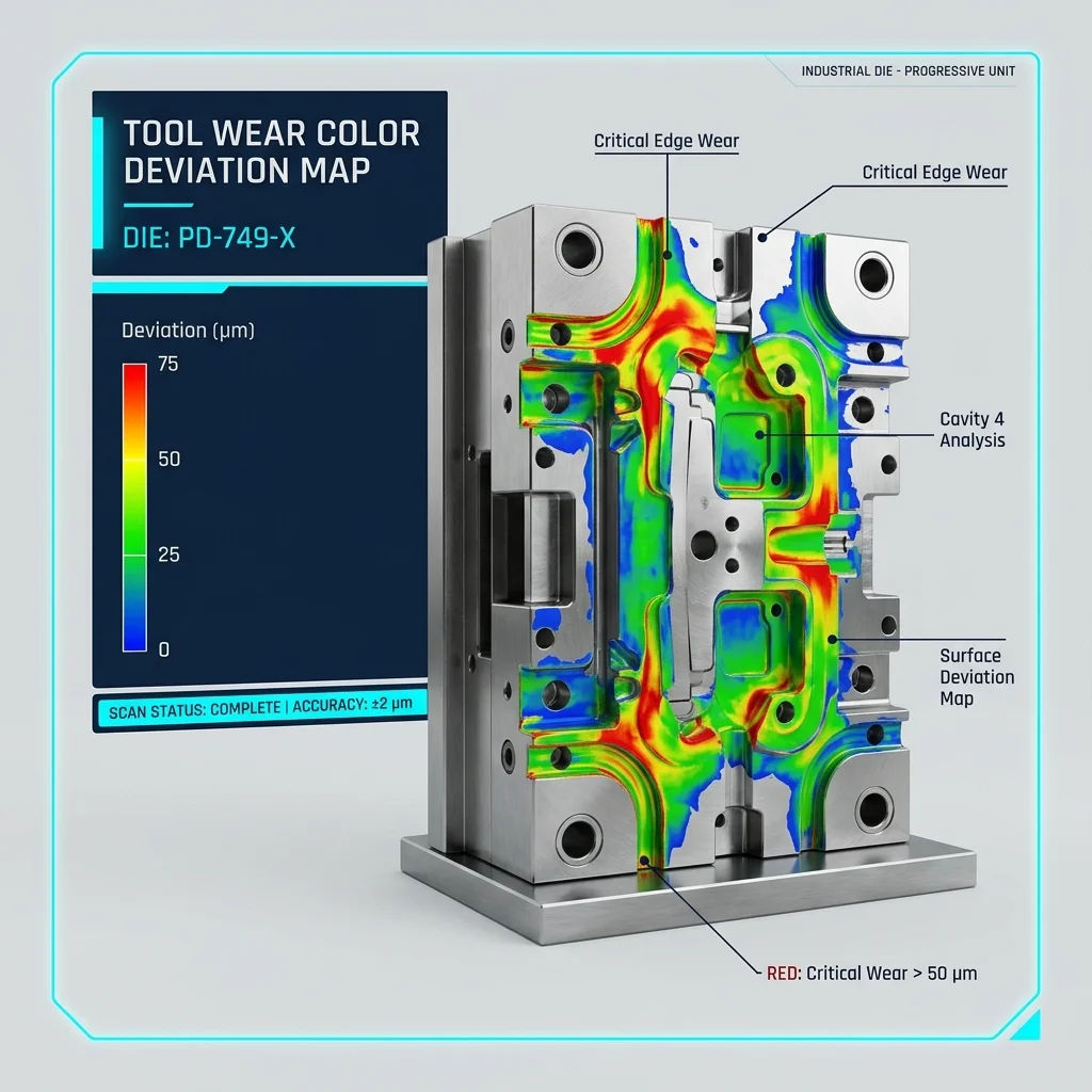
Dimensional Drift
Production runs induce microscopic wear. Catch tolerance deviations instantly before mass production fails.
Wear Tracking
Scan and compare against baseline CAD to visualize degradation with stunning color-mapped precision.
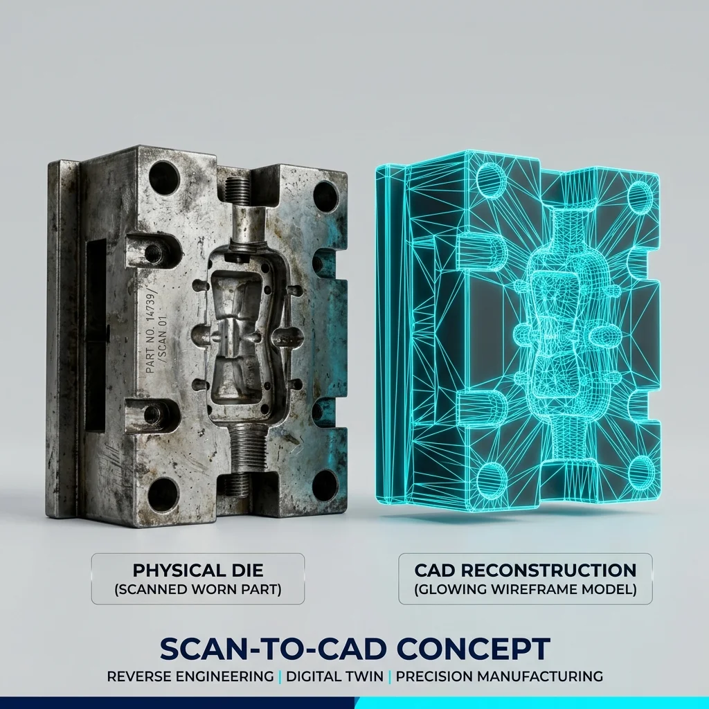
Obsolescence
Recreate perfect manufacturing data from heavily worn legacy tools that have no CAD documentation.
Core Capabilities
End-to-end metrology and design engineering support specifically tailored for the heavy tooling sector: four capability areas — scanning, reverse engineering, on-site metrology, and documentation — cover a tool from first tryout to end-of-life reproduction, backed by laser tracker and portable CMM hardware for tools too large to move.
3D Scanning & Tryout
Expedite your T0/T1 tryout cycles. We capture millions of points across freeform surfaces of injection moulds and stamping dies, providing full-surface dimensional validation against nominal CAD.
Parametric Reverse Eng
Transform physical tools lacking data into fully parametric, feature-based CAD models. We correct existing wear and damage, delivering pristine native files for reproduction.
On-Site Portable Metrology
Large press dies cannot be easily moved to a lab. We bring metrology to your shop floor. Our dynamic referencing optical CMMs ignore environmental vibrations to deliver lab-grade accuracy on-site.
2D Drafting & GD&T
Convert 3D scan data into complete manufacturing packages, including detailed 2D engineering drawings with precise tolerancing, surface finish callouts, and BOM generation.
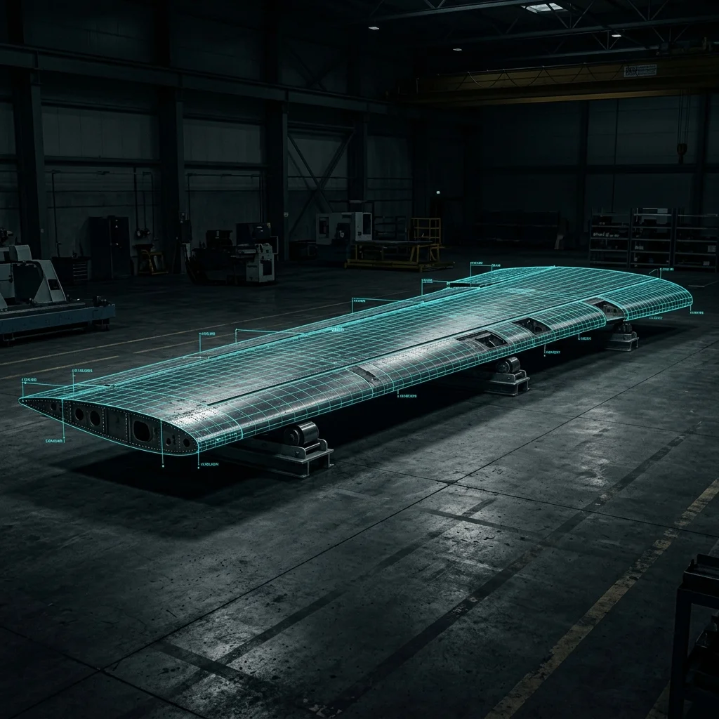
Inside The Inspection Workflow
From optical scan capture to wear mapping and shop-floor execution.
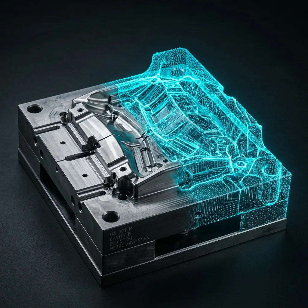
Predictive Maintenance
Identify exact wear locations to guide laser cladding and welding repairs, preventing catastrophic failure.
Lifecycle Support Strategy
We secure every phase of your tooling lifespan.
Tool Validation & Tryout
First article inspection & T0 tryout tuning to achieve production-ready status faster.
Periodic Quality Checks
Scanning random batches to ensure output parts remain within geometric tolerance.
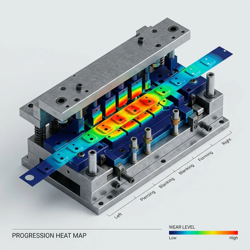
Wear Mapping
Mid-life tool scanning to generate precise degradation heatmaps against the baseline.
Obsolescence Recovery
Complete reverse engineering of the tool at end-of-life to manufacture identical replacements.
Why Manufacturers Partner With Us
Full Lifecycle Coverage
We don't just scan; we support you from T0 validation through mid-life wear analysis to end-of-life reverse engineering.
Lab-Grade Accuracy On-Site
Our MetraSCAN and HandyPROBE systems allow metrology-grade measurement right on your shop floor, ignoring vibrations.
Predictive Data
Stop guessing when a tool will fail. Our deviation tracking shows you exactly how fast and where tools are wearing.
Fast Response Pan-India
Machine downtime is expensive. Our distributed engineers deploy rapidly to get your production back online.
What is Tool & Die Engineering Services India?
Tool and die engineering services support the tooling lifecycle with 3D scanning, tool wear analysis, reverse engineering, CAD documentation, and portable CMM inspection, helping tool rooms validate, maintain, refurbish, and reproduce dies and stamping tools with confidence.
When to Select This Service
Choose tool and die engineering support when precision tooling requires precision data -- for wear tracking, refurbishment planning, reverse engineering of legacy dies, or building CAD documentation for tools that never had it.
Technical Capabilities & Verification Standards
Verified engineering parameters, hardware precision, and compliance benchmarks applied across all deliverables.
| Engineering Parameter | APJ 3D Capability & Precision Range | Compliance Standard / Verification |
|---|---|---|
| Scanning Hardware | Creaform HandySCAN 3D, MetraSCAN 3D, ZEISS GOM ATOS Blue Light, FARO Laser Trackers | VDI/VDE 2634 Part 3 Certified |
| Volumetric Accuracy | Up to 0.020 mm (20 µm) + 0.040 mm/m over large volumes | ISO 17025 Traceable Calibration |
| Part Size Range | From 10 mm precision clips up to 20+ meter automotive bodies & aircraft structures | Portable On-Site & Lab Inspection |
| Surface Resolution | Mesh grid resolution down to 0.050 mm (50 µm) | High-Density Micro-Feature Capture |
| Output Deliverables | High-density STL, OBJ, PLY, Native STEP/IGES CAD, Colour Error Deviation Maps, PDF Reports | ASME Y14.5 Inspection Reports |
| Measurement Speed | Up to 1,300,000 measurements/second (Dual Blue Laser Cross) | Rapid Real-Time Data Acquisition |
| Turnaround Time | On-site scanning: Same-day / 24h; Full CAD/Inspection reports: 2 to 4 business days | Pan-India On-Site Mobilization |
Frequently Asked Questions
Can you perform 3D scanning on-site at our manufacturing plant?
Can you perform 3D scanning on-site at our manufacturing plant?
How do 3D scanning and reverse engineering differ?
How do 3D scanning and reverse engineering differ?
What is a color deviation inspection map?
What is a color deviation inspection map?
Can dark, shiny, or transparent surfaces be scanned?
Can dark, shiny, or transparent surfaces be scanned?
What accuracy can we expect for automotive and aerospace components?
What accuracy can we expect for automotive and aerospace components?
Need Engineering Support for Your Tooling Project?
Share your tooling type, CAD availability, and inspection requirement. We'll outline the exact scanning approach, timeline and execution strategy.